PYTHON – Let the „Monty-language” enter Automation: Part 4
Follow article
 Dave from DesignSpark
How do you feel about this article? Help us to provide better content for you.
Dave from DesignSpark
Thank you! Your feedback has been received.
Dave from DesignSpark
There was a problem submitting your feedback, please try again later.
Dave from DesignSpark
What do you think of this article?
So now you are here in part 4, if you need a recap please review part 1, part 2 and part 3.
We will run the GUI for our system on the same RevPi system which runs the PID controller, and it can be accessed with any browser. But first of all, we need to install an MQTT broker.
We get back to our PuTTY session and use the following command to install an MQTT broker on this system:
sudo apt-get install mosquitto mosquitto-clientsWhat is the task of an MQTT broker? It accepts values which come from clients. The clients “publish” such “metrics” under a “topic” (kind of a named container). Other clients may “subscribe” to such topics. As soon as a new value is sent to the broker, it forwards this value to all clients who have subscribed to the topic of the value. You could secure this data distribution by encryption, but for this demonstration, I waive encryption to keep things easy.
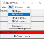
The RevPiPyLoad service can be configured to publish all IO values from the process image marked with “export” to an MQTT broker. Let’s go back to the RevPiPyControl Application and open “PLC” -> ”PLC options…”. You get a new window like this:
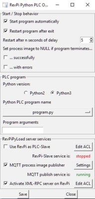
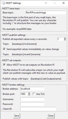
Set the mark at “MQTT process image publisher” in the “RevPiPyLoad server services” section and click on “Settings”. Please use the setting of the screen dump for this demonstration. If you use an MQTT broker anywhere in your Network, you should consider prolonging the publish interval from 1 second to, e.g. to 10 seconds.
Click two tiomes “Save” and your RevPi immediately starts publishing the metrics from the process image to the Mosquitto MQTT broker. Any Client could subsribe to the topics
- RevPiProcessImage/event/PWM_heater1
- RevPiProcessImage/event/PWM_heater2
- RevPiProcessImage/event/Temp10
- RevPiProcessImage/io/PWM_heater1
- RevPiProcessImage/io/PWM_heater2
- RevPiProcessImage/io/Setpoint
- RevPiProcessImage/io/Temp10
to receive the published values.
We will use Node-Red as MQTT client to subscribe to these values and to display them on a UI. Node-Red is a wonderful “drag&drop stye software creation tool”. It was developed by IBM who gave it into the open source pool of the JS-Foundation. The IDE works browser-based, and you can easily set up so-called “flows” of messages. All you need to do is drag & drop “node” components out of a selection of predefined nodes into a flow. You then“wire” (connect) the node outputs to node inputs using your mouse. All nodes can be configured with parameters by clicking on them.
Node-Red is pre-installed on every RevPi, and this server service just needs to be started. With the following commands (use your PuIIY session) you permanently enable and start Node-Red:
sudo systemctl enable nodered.service
sudo systemctl start nodered
If you have programmed “flows” and saved (“deployed”) then, they will be automatically executed after booting (you do not need to reboot now, Node-Red has already been started manually).
We need to add new “nodes” to the Node-Red IDE, so we install “npm” (the packet manager for the JavaScript runtime system “Node.js” with the following command:
sudo apt-get install npmYou are nearly done - we just need to set up the flow. I can reach the IDE with my browser from the PC at the following IP and port address: http://192.168.0.241:1880 (you need to replace it with your RevPi’s IP). The IDE language is the preferred language of your browser.
On the left sidebar, you find all “nodes” which you can drag & drop on the empty flow in the middle of the window. We need to add the dashboard (UI) nodes. Thanks to npm, this can be quickly done by clicking on the menu icon (top right corner) and choose “Manage Palette”. Choose the “install” tab and enter “dashboard” as the search string. Give the system some time to get the results, choose “node-red-dashboard” and click on “install”. Then close the Palette Manager and refresh your browser (F5). Now you will find the new installed nodes on the left side palette under the title “dashboard”.
Go to section “input” in the palette and drag and drop the mqtt node onto the flow area. Double click on the node to configure it:
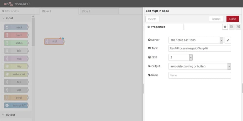
Enter the topic “RevPiProcessImage/io/Temp10” and click “Done”. We want the temperature to be displayed in °C, and therefore the metric from the process image (which we receive from the MQTT broker) needs to be multiplicated by 10. This can be done with a “function” node (the first node under section “function”. Drag & drop it right of the mqtt node and double click on it for configuration:
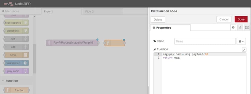
The “Function” editor allows entering Java code. All nodes know the object “msg” which is the message flowing into it and sent out by it. To change the content of a message we use its “payload” (the primary content of all node messages, you could add deliberately any new content variable). So msg.payload = msg-payload/10 does the job we need to be done. Click on “Done”.
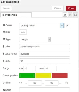
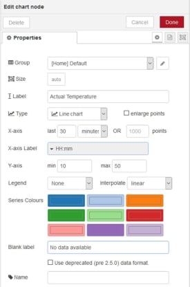
Now add two dashboard nodes and drag & drop them right of the function node:
The gauge node and the chart node are configured like this:
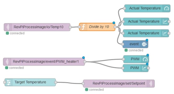
Now we connect (“wire”) the nodes by clicking on the little circles at the right edge of a node (=output of the node), let the mouse button pressed and draw a line to a left edge circle of a node (=input). As you can see, you can use multiple wires at one circle:
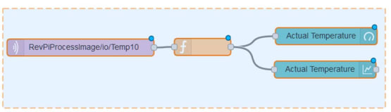
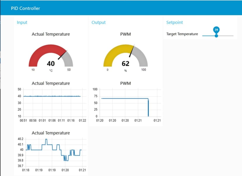
The blue dots signal unsaved (“undeployed”) nodes. So we click on “Deploy”, and our flow is executed. Whenever an MQTT message is received, its value is multiplied by 10 and used as the input value for the UI element. But how can we see the result? This is pretty simple: Just open a browser window at http://192.168.0.241:1880/ui (please replace the IP with your RevPi’s IP):
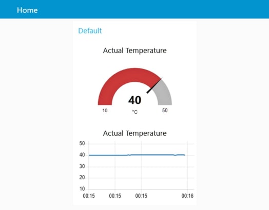
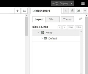
Use the right side menu “dashboard” to edit the UI page name (“Home”) and group name (“Default”) to your preferred text:
I leave adding a chart and gauge for the PWM value as a learning task for you. You should use the MQTT topic “RevPiProcessImage/event/PWM_heater1”.
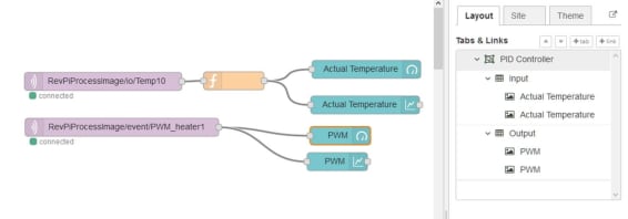
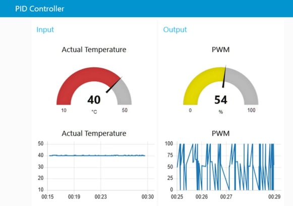
If you are still happy with our demonstration project, you can follow me adding a setpoint slider:
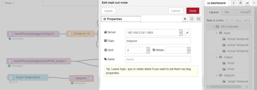
I drag and drop a slider to the flow and add it to a third UI group called “Setpoint” (I use a range of 30 to 50 °C with a step size of 0.5 and output set to “only on release”). I connect this node with an mqtt output node. The mqtt output node is configured with the publish-topic “Setpoint”:
We use our Python software to subscribe to this value and use it as a setpoint for the PID-function call instead of using a constant value. Therefore we need to install the Python MQTT client library called “paho mqtt”. Use your PuTTY and enter
sudo pip3 install paho-mqttThen edit the Python code. Add the import statement for the library. Add a so-called “call-back” function with the “def” statement. This function is called by the Paho MQTT client whenever a subscribed topic receives a new message from the MQTT broker. With five additional lines of code, we initialise and start the MQTT client and subscribe to “Setpoint”.
from simple_pid import PID
import revpimodio2
import time
import paho.mqtt.client as mqtt

def on_message(client, userdata, message):
    TempController.setpoint = int(float(message.payload)*10)

client = mqtt.Client("myplc")
client.connect("localhost")
client.on_message=on_message
client.subscribe("Setpoint",2)
client.loop_start()

TempController = PID(5,0.13,10.5,sample_time=0.1, setpoint=400, output_limits=(0,100))
rpi = revpimodio2.RevPiModIO(autorefresh=True)

while True:
    Temp = rpi.io.Temp10.value
    pwm = TempController(Temp)
    rpi.io.PWM_heater1.value = int(pwm)
    rpi.io.PWM_heater2.value = int(pwm)
    time.sleep(0.05)
Now let’s save this script in the “auto execution folder” of RevPiPyLoad, which is “/var/lib/revpipyload” and name it “program.py” (these two parameters could be changed in the configuration file you have edited at the beginning of our little project). You cannot do this with “save as …” in the IDLE editor because the path “/var/” needs admin rights to write files into. Therefore we use PuTTY for the last time and enter the Linux command
sudo mv ~/myplc.py /var/lib/revpipyload/program.py“Sudo” is the magic word which gives you admin rights for the execution of this single command.
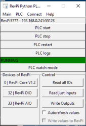
In the RevPiPyControl window, click on “PLC restart, and the red error message should vanish. A green bar indicates the successful start of the Python PLC script:
I hope you could follow this step by step instruction successfully. Although you had to do lots of configuration, we ended up with only 19 lines of Python code (I removed the debug print code). Why not giving the IBM Watson node a try? You will be thrilled how easy it is to get values up in the cloud (IBM gives you a free “Quickstart” access for experimental purposes). Go to this address to see if my device is online and whats’s my office’s temperature. If you experience any trouble while trying to build your RevPi Python controller, leave a comment here or send me a message. Sven Sager, the author of RevPiModIO, would like to share some ideas of how to make a professional version out of this demonstration. He will probably post his thoughts soon in the comments. So stay tuned if you like to get deeper into Python for automation.
____________________________________________________________________________
____________________________________________________________________________
Sven Sager, the author of the RevPiModIO library and other tools mentioned in this article, has kindly sent this comment:
Just some thoughts about the „while True“ loop:
If we are on a dedicated micro controller – arduino and things like that, we have to use some kind of endless loop to keep our program running. Handle all the hardware stuff, calculate values, do some input output and so on – Main thing: we are the only process on that CPU.
But now we are using a Debian based Revolution Pi with a Linux kernel. Our program is not the only one on that CPU, and we have to understand how an operating system is handling processes.
Startup our program is very simply. It is done by RevPiPyLoad, Systemd, via shell, double click, or whatever. So now our program is running in our “while True” loop and does all the stuff we want – everything is fine, till we want to exit the program!
Doesn’t matter if we Ctrl+C, push “Stop PLC” button in RevPiPyLoad or shut down our Revolution Pi. The operating system’s penguin is sending the "TERM" signal to our program, a friendly request to quit! Now we should leave our “while True” loop, save some data, disconnect from databases or do some other clean up stuff. BUT: We can not leave “while True”, we can not quit our program and the penguin pecks us with his beak sending a "KILL" signal! No matter if we are writing a file, saving data to a database, communicate to a network partner – It's over now! No chance to finish the file, commit changes or disconnect.
So, if you are developing programs, services, or whatever, take a look to signals (link 1 below).
In our case, we are using RevPiModIO, and I included all that signal stuff to the library. We just have to activate the signal handling by calling ".handlesignalend()" right after creating our rpi object (link 2 below). If our program gets "SIGTERM", RevPiModIO will set an "exitevent", which we can use to leave our endless loop. Just change “while True:” to “while not rpi.exitevent.is_set():”.
RevPiModIO has some more features to create professional control programs for the Revolution Pi. If we take our example, we have a cyclic program. The lines in our while loop are called every 50 milliseconds, but not in sync with the process image!
The cycle of a PLC should read all inputs from process image, run your cyclic function with frozen input values, write all outputs to process image and start over again. Why is this important? Simple: If you set 14 outputs to the value of one input, you will expect, that the outputs have all the same value. But if we use “while True” it could happen, that the input changes its value after we set 10 outputs, so the next 4 outputs have a different value.
With RevPiModIO we can use the ".cycleloop" (link 3 below)! Just replace the “while True:” with “def cycle(cycletools):”, remove "time.sleep(0.05)" and call "rpi.cycleloop(cycle, cycletime=50)" on the end of file, that’s it! RevPiModIO will call your function every 50 milliseconds. Of course, ".handlesignalend" will work, too!
So this is our modified example program, which handles operating system signals and handle the cycle function in sync with process image – As a further side effect, the run time of the function is monitored and you get some cycletools to work with (link 4 below)!
from simple_pid import PID
import revpimodio2
import paho.mqtt.client as mqtt
def on_message(client, userdata, message):
TempController.setpoint = int(float(message.payload)*10)
client = mqtt.Client("myplc")
client.connect("localhost")
client.on_message=on_message
client.subscribe("Setpoint",2)
client.loop_start()
TempController = PID(5,0.13,10.5,sample_time=0.1, setpoint=400, output_limits=(0,100))
rpi = revpimodio2.RevPiModIO(autorefresh=True)
rpi.handlesignalend()
def cycle(cycletools):
Temp = rpi.io.Temp10.value
pwm = TempController(Temp)
rpi.io.PWM_heater1.value = int(pwm)
rpi.io.PWM_heater2.value = int(pwm)
rpi.cycleloop(cycle, cycletime=50)