Pulse Oximeter design solution from Microchip
Follow article
 Dave from DesignSpark
How do you feel about this article? Help us to provide better content for you.
Dave from DesignSpark
Thank you! Your feedback has been received.
Dave from DesignSpark
There was a problem submitting your feedback, please try again later.
Dave from DesignSpark
What do you think of this article?
The ongoing COVID-19 pandemic is recognised to be significantly more dangerous than its predecessors mainly due to the absence of noticeable symptoms in the early stages of the infection. This led to the rapid spread of the virus, causing dramatic strain to health care systems in many countries. With only severe cases being admitted to hospitals, most patients with mild to moderate symptoms are treated at home. The self-monitoring of vital signs during home isolation might help patients to detect any changes in their condition reducing the risk of progressing into a serious or critical stage.
Oxygen saturation (SpO2), along with other vitals such as body temperature, respiratory rate, blood pressure, and heart rate, is periodically monitored by the healthcare professionals to diagnose and treat patients with respiratory diseases within hospitals. The device that measures the oxygen content in the bloodstream is called a pulse oximeter. Pulse oximeters can be designed as a part of bedside vital sign monitoring equipment or as a stand-alone medical device for at-home use.
In this article, we will present a pulse oximeter design solution from Microchip with all the supplementary material, including application note and source code, as well as product recommendations. This is a good starting point for those, who are interested in building a prototype for their first medical device.
What is it?
A pulse oximeter is an optoelectronic device that monitors how much of the hemoglobin in the bloodstream is carrying oxygen. The operation of a pulse oximeter is based on light absorption characteristics of oxygenated hemoglobin (HbO2) and deoxygenated (Hb) hemoglobin at two different wavelengths: red light (600-750 nm) and infrared light (850-1000 nm). Oxygenated hemoglobin absorbs more infrared light than red light, whereas deoxygenated hemoglobin absorbs more red light than infrared light. The pulse oximeter uses a clipper type of probe with red and infrared LEDs on one side and a photodiode on the other side. The clipper is attached to the patient’s finger or ear, and the light is transmitted through that part of the body. The percentage of oxygen in the blood can be calculated as a ratio of the red and infrared light detected by the photodiode.
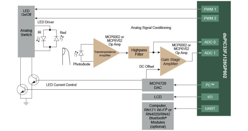
LED Driver
Two LEDs are controlled by sending PWM signals from the microcontroller. Red and infrared lights are turned on and off one after another with a specific interval. An analog switch is used to switch between those two signals. MCP4728 (823-1110) 12-bit DAC can be utilised to control the current through LEDs, and hence the intensity of them. Commercially available DS100A SpO2 probe from Nellcor, consisting of a red LED, IR LED and a photodiode, was selected for this demo board.
Analog Signal Conditioning
The main purpose of the analog signal conditioning circuit is to modify the signal from photodiode for it to be ready to be processed by ADC. Firstly, this will require the conversion of the current detected by the photodiode into a usable voltage using a trans-impedance amplifier (TIA). A TIA can be built by adding an external feedback resistor and capacitor to an operational amplifier. Microchip’s MCP6002 (667-4339) dual general-purpose amplifier can be selected for this purpose. The next stage of the signal conditioning circuit is designed to remove noise artifacts due to ambient light in the background. A basic high pass filter consisting of a single resistor and capacitor should be sufficient. Lastly, a gain stage amplifier with pre-selected gain and DC offset is implemented to properly match the signal level into the input range of microcontroller’s ADC. MCP6002 amplifier can be used here as well.
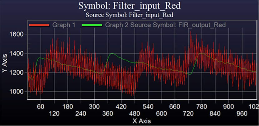
Processing
DSPIC33FJ128GP802 (178-4858) Digital Signal Controller (DSC) is used for this demo board. The internal ADC of the dsPIC DSC takes samples from the output of the analog signal conditioning circuit. The samples are measured during each LED’s on and off-time periods. 513th order digital FIR Bandpath filter is implemented using Digital Signal Processing (DSP) engine integrated into dsPIC DSCs. The filtered output can be used to calculate SpO2 and pulse rate. FIR filter specifications are available in the supplementary materials section of this article.
User interface
There are several options to access SpO2 and pulse rate data from the microcontroller. It can be sent directly to the computer through a UART port with the PICkit™ Serial Analyzer (038-1554) . Alternatively, the data can also be sent to a Wi-Fi® or Bluetooth® module via the UART port.
The dsPIC DSC comes with an in-built PWM module for driving the LCD display. Basic monochrome LCD display such as 16x2 Character LCD display (532-6436) from Displaytech should be a good starting point for this design.
Power management
A portable pulse oximeter relies on a robust power management solution for reduced battery energy consumption. MCP1640 (738-6241) synchronous PFM/PWM Boost Regulator is implemented to supply the microcontroller with regulated +3.3V.
The instructional video from Microchip below explains how the demo board works in more detail:
The supplementary materials to this article consist of AN1524 application notes as well as source code to the algorithm used by the microcontroller.
Are you involved in medical device design and manufacture?
Let us know in the comments if you are involved in the response to the COVID-19 response in pulse oximeter design.