Assembling a Discrete 555 Timer
Follow article
 Dave from DesignSpark
How do you feel about this article? Help us to provide better content for you.
Dave from DesignSpark
Thank you! Your feedback has been received.
Dave from DesignSpark
There was a problem submitting your feedback, please try again later.
Dave from DesignSpark
What do you think of this article?

Building the Evil Mad Scientist 'Three Fives' Kit.
Previously I had a go at Getting to Grips with 555 Timer Basics and built two circuits using the Engineers Mini Notebook – 555 timer IC circuits by Forrest M Mimm. In that post I looked at what a 555 Timer is and some of the ways which it can be used.
As I really enjoyed working with 555 timers I wanted to have a look at them more in depth. I was shown the 'Three Fives' discrete timer kit by a colleague and thought this would be a really fun project to follow on from my previous post with.
What is the 'Three Fives'?
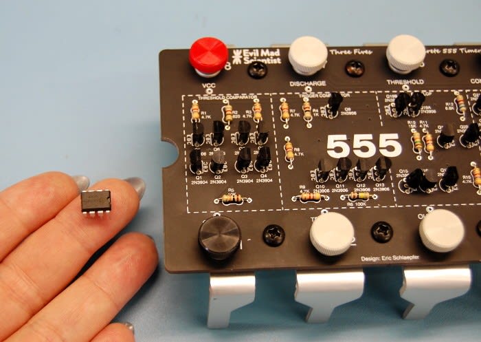
Evil Mad Scientist have produced a really exciting kit which is a giant 555 Timer circuit which you assemble yourself to then use in projects. As the 555 timer has been one of the most popular ICs to be used in electronics, I was really looking forward to assembling a kit which has all its inner workings on a much larger PCB.
Assembling the Kit
For anyone who as read any of my previous kit assembly posts they will know that I love to solder and assemble PCBs, so from the word go I was eager to get started! This kit contains 17 resistors and 26 transistors in total!
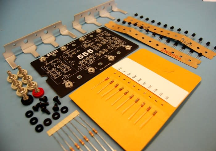
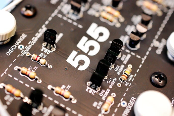
To begin with I laid all the components out so that I knew what I had to work with. I began by soldering the 17 resistors in place on the board. One particularly nice thing about this kit being that all the resistor values are marked in silkscreen on the PCB, and the 10 different values come on a piece of card with the resistances marked at the side and the seven 4.7K resistors are kept separate in their own bag. This saved time so I didn’t have to use a resistor colour band card or multimeter.
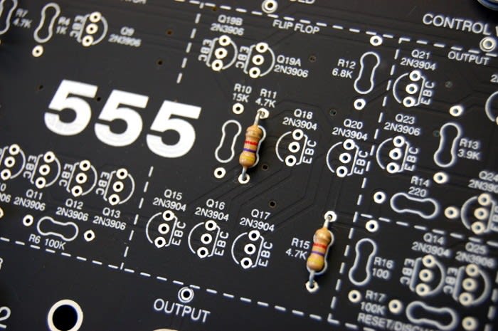
I next started inserting all the 2N3906 transistors in place, again according to the silkscreen markings. One thing to be sure of when inserting transistors to be soldered in place is that the emitter, collector and base are all of the correct orientation. After the first lot of transistors were in place I then added the remaining thirteen 2N3904 transistors, before soldering all of these in place.
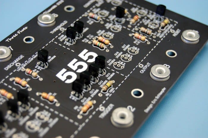
Personally I prefer placing all of one type of component on the board before soldering them all together, however, some people do prefer to solder each component individually. It's really important not to create any solder bridges between the legs of the transistors as this will create a short, as the legs and pads are very close together it is really easy to make a solder bridge, so it's important to take extra care.
When I’ve finished soldering a board like this I find it useful to check the connections with a magnifying glass. This is really helpful for two main reasons: Firstly you can check that the solder has flowed properly on the pad and made a good connection; secondly you can see clearly that there are no shorts between pads on the PCB.

Once I was sure all the connections were correct I then added the hardware to the board before I had a go at testing it!

Putting It to the Test
Before I used the discrete 555 timer in a circuit I wanted to first test this with a normal 555 timer IC. I decided I would just use a simple circuit which would make an LED blink.
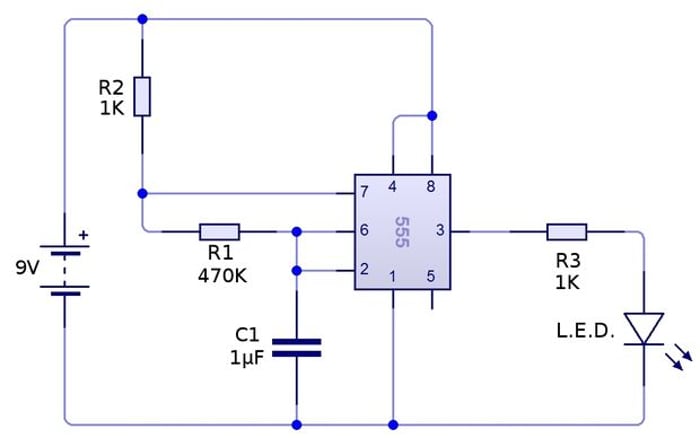
Image Source: http://www.instructables.com/
The 555 timer IC circuit worked fine once assembled, so the next step was to attach wires from the discrete circuit to the breadboard.
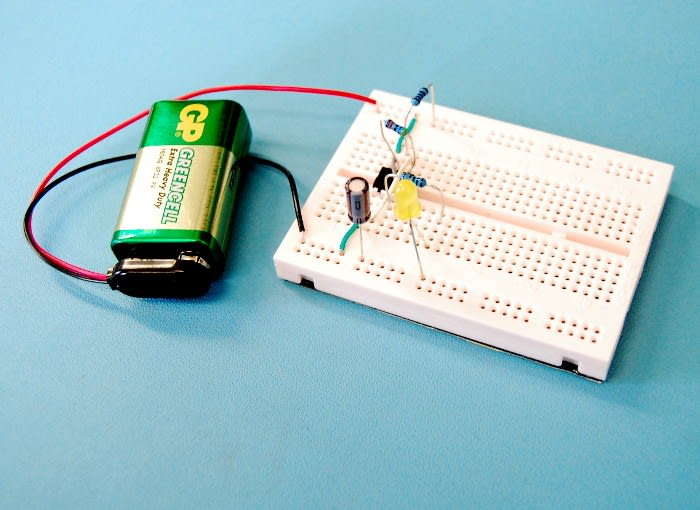
Once the discrete circuit was wired up with the breadboard I connected this to a 9V battery and saw the LED blinking, success! This meant that there were no faults with my assembly of the kit, so it was ready to be used in projects!

Before integrating the discrete 555 into any more projects I decided I wanted to have a closer look at the internal operation. On the silkscreen there are five sections clearly labelled; threshold comparator, trigger comparator, flip flop, output and reset/discharge.
Comparators
The 555 timer circuit contains two comparators – a comparator is a device which compares two currents or voltages and produces an output signal indicating which is larger.
One compares threshold voltage with a reference voltage of + 2/3 Vcc. And the other compares the trigger voltage with a reference voltage of + 1/3 Vcc. Hence why the board has both threshold comparator and trigger comparator sections.
Output
The output of a 555 timer can be in one of two states at any one time, making this a digital output. This part of the circuit can either be connected to the input of other ICs, or with the addition of a few extra components this can control other devices. The output will either be in a 'high' state where this at at the input voltage, or it will be in a 'low' state at 0V.

Flip flop
This is a bistable multivibrator which can be made to change state based on the signals applied to the input(s) and will have either one or two outputs. There are several different types of flip flop, in the case of a standard 555 timer this is usually an SR (set-reset) Flip Flop.

Reset/Discharge
An external capacitor is connected to the discharge pin and this controls the timing interval.
The reset pin is used to restart the timing and is active low, so this would normally be connected to Vcc. If the timer is interrupted via reset it needs to be restarted again via the trigger.

I've really enjoyed looking at the basic internal operation of 555 timers. I think a lot of the time people often don’t think about what actually goes on inside an IC, so I found it really interesting to learn about this with one of the most popular ICs around!