FORTHdsPIC and a Kill Switch
Follow articleHow do you feel about this article? Help us to provide better content for you.
Thank you! Your feedback has been received.
There was a problem submitting your feedback, please try again later.
What do you think of this article?
In my last post I described how to get FORTdsPIC running on wheels, seeking out light while avoiding bumping into the furniture. In other words making it an autonomous vehicle, admittedly somewhat lacking in intelligence, but able to make directional decisions based on data from its sensors. A feature of such a vehicle is that it starts working from power on, so how do you bring it to a stop without just turning the power off?
WARNING: What follows may seem to be a mind-numbingly tedious diatribe on the engineering necessary to achieve a simple end: make the microcontroller stop running the user’s programme by pressing a button. How difficult could it be? Not difficult at all, when you realise the electrical signal generated by pressing the button – as seen by the processor – is very different from what you might imagine.
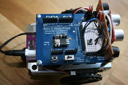
'Kill-Switch' on the breadboard block
Back to the Problem
Another snag is that you can’t stop the program without plugging in the PICkit 3 debug tool and erasing the whole chip from MPLAB. Then you have to re-program the FORTHdsPIC code. Power switches may be difficult to reach and in any case you might want RAM data to remain intact for diagnostic purposes. Of course if the program is running in Flash memory on a mobile robot there won’t be a PC connected to command a stop either. Hitting the processor ‘Reset’ button won’t help – that’s just the same as cycling the power switch off and on again. What we need is a button that forces the user’s program to abort and wait for a terminal to be plugged in again. The first command can be ERASE to remove the embedded code. Otherwise pressing Reset will start it running again. A first idea might be to connect a pushbutton to a spare GPIO pin set for input, and have the user program periodically check to see if it’s been pushed. That’s OK, but I wanted a means of exiting an endless BEGIN….AGAIN loop which wouldn’t require special user code to monitor a pushbutton. The answer is a button that initiates an external program interrupt. A number of GPIO pins can be set up as external interrupt inputs and I selected INT0 on Port B7 – pin 16.
Floating Inputs
In principle all we have to do is connect a simple pushbutton between pin 16 and 0v (Gnd). Pressing the button will take the input down to logic 0 (a falling edge); releasing it will allow the input to rise back up to logic 1 state (a rising edge). INT0 can be set to activate on either edge causing a call to an interrupt service routine (ISR) which will force a return to the command prompt. That’s it. Job done. Er..no. As is so often the case, it’s not as simple as that: unlike other circuits we have attached to inputs this one is purely mechanical. To start with, the input is going to need a ’Pull-Up’ resistor to the power-supply rail. While the button is not being pressed, the input is just ‘floating’ as nothing is driving it up or down. The resistor simply ensures that logic 1 is present until you press the button and drag it down to logic 0. A floating input has very high impedance and is quite good at acting as an antenna for stray electrical ‘noise’, in this case causing random unwanted interrupts. OK so that’s sorted; write the setup code for the interrupt and the ISR which will respond to say a falling edge, add these to FORTHdsPIC and the Forth programmer has a means of stopping an unresponsive program with no keyboard connected. Well…not really.
Bouncing Switches
Unfortunately there is another problem with mechanical switches: they don’t change state cleanly. When you press the button, the contacts close, but then ‘bounce’ open and closed again…and again. This can go on for several milliseconds and each bounce generates another interrupt. The same thing happens again when you release the button. For a detailed examination of the phenomenon read this paper: ‘A Guide to Debouncing’ which contains some ‘scope pictures of real signals. What it means in this case is multiple jumps to the quit routine which probably won’t matter beyond irritating repeated command prompts on the terminal if it’s connected. It may only be cosmetic but I wanted a clean, single quit. Debouncing techniques are broadly divided into hardware and software implementations. Hardware solutions usually involve filtering out the oscillations before the signal is presented to the interrupt pin; software remedies tend to be based on delay loops that wait for all the fuss to die down before responding.
Debouncing the Stop button with some Bare-Metal Code and a resistor
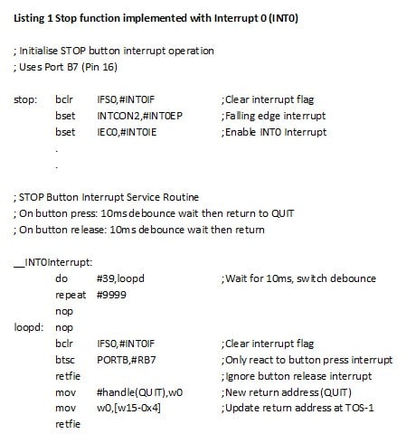
Listing 1 shows the setup code and the ISR for the Stop button using external interrupt INT0. A small piece of hardware – a 10kohm pull-up is also required. The setup code consists of just three lines: the first clears any pending interrupt flag, the second selects interrupt on falling edge and the third enables the interrupt. The ISR is very short incorporates a programmable delay. The instructions DO and REPEAT form a fully-programmable delay timer in conjunction with the next two NOPs. The two numbers 39 and 9999 yield a delay of 40000 clock cycles or 10ms assuming a 40MHz processor clock. Normally a software delay timer would involve a lot more code even if one of the on-board Timers were used. Here, an outer DO loop is set up to execute 40 times the inner REPEAT instruction which itself executes 10000 times. After the 10ms wait which should be enough, even for a fairly ropey button, comes a seemingly pointless test to see if the input has settled low or high – button pressed or released. The code is there to ensure that ‘bounces’ on release are ignored and only the very first falling edge causes a jump to the Quit routine. That ‘jump’ is achieved by replacing the current interrupt return address, the second item down on the machine stack after the processor status word, with the address of Quit. The return from interrupt (retfie) instruction does the rest.
Although it works, this solution does involve the addition of the pull-up resistor and that’s mildly annoying. As it happens, the dsPIC has another trick up its sleeve when it comes to detecting things happening on the GPIO pins: Change Notification.
Debouncing with just Bare-Metal Code
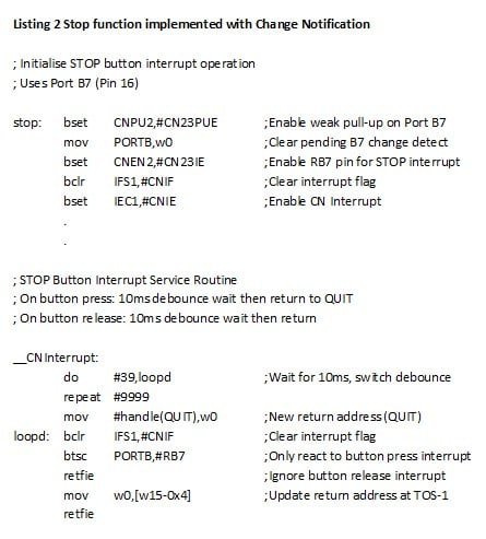
Listing 2 looks remarkably similar to Listing 1, the main changes being to the setup program. The CN system can be activated to generate an interrupt whenever the selected GPIO pin changes state in either direction. The same basic ISR for INT0 will work for the CN version. What’s the advantage? When you activate CN on a port pin, another rather useful feature becomes available: a built-in ‘weak’ pull-up. Weak means that it has a relatively high resistance value avoiding high current consumption. So an entirely software solution is possible for our essentially hardware problem after all. As an aside you may have noticed that the NOPs are missing from Listing 2. This is because any single-cycle instruction may be used, so long as it doesn’t change anything every time it is executed. The two selected will change a flag and update a register with a new value once only no matter how many times they execute in the DO and REPEAT loops. So that’s a couple of lines of code saved.
If you're stuck for something to do, follow my posts on Twitter. I link to interesting new electronics components and development kits (some of them available from my employer!) and retweet posts I spot about robot, space exploration and other issues.


