Processing數位互動介面開發軟體應用 –結合 Arduino 硬體控制
关注文章
 戴夫来自 DesignSpark
你觉得这篇文章怎么样? 帮助我们为您提供更好的内容。
戴夫来自 DesignSpark
Thank you! Your feedback has been received.
戴夫来自 DesignSpark
There was a problem submitting your feedback, please try again later.
戴夫来自 DesignSpark
你觉得这篇文章怎么样?
|
作者 |
曾吉弘 |
|
難度 |
普通 |
|
材料表 |
1. Arduino UNO |
上一篇文章介紹了 Processing 的基礎應用,本篇文章要介紹如何讓 Processing 透過 USB 傳輸線來連結 maker 相當喜愛的 Arduino Uno 開發板,另外也會介紹最近相當有人氣的 LinkIt 7697 開發板。做法有兩種:
- 運用 Arduino 的 StandardFirmata,好處是 Arduino 端不需要再寫程式,只要從 Processing 端發送指令即可,但缺點是彈性較低且較難客製化,例如特殊的感測器就無法直接讀取數值。
- 自行定義USB發送的訊號,好處是可以做到任何您希望的功能。缺點就是程式碼需要對應,Processing 修改了任何地方,Arduino 端都需要做對應的修改。
現在就讓我們看看怎麼做吧。
Arduino 端
在此使用 Arduino Uno 開發板。請下載 Arduino 環境,在此使用 Arduino 1.8.5,更新或再舊一點的版本應該都可以用,StandardFirmata 算是相當早期就有的做法了。燒錄完成之後,請讓 Arduino 接著電腦放著就可以了。

Processing端
請開啟 Processing 官方網站的下載頁面,根據您所使用的硬體平台下載對應的版本,如果還沒下載請參考上一篇。
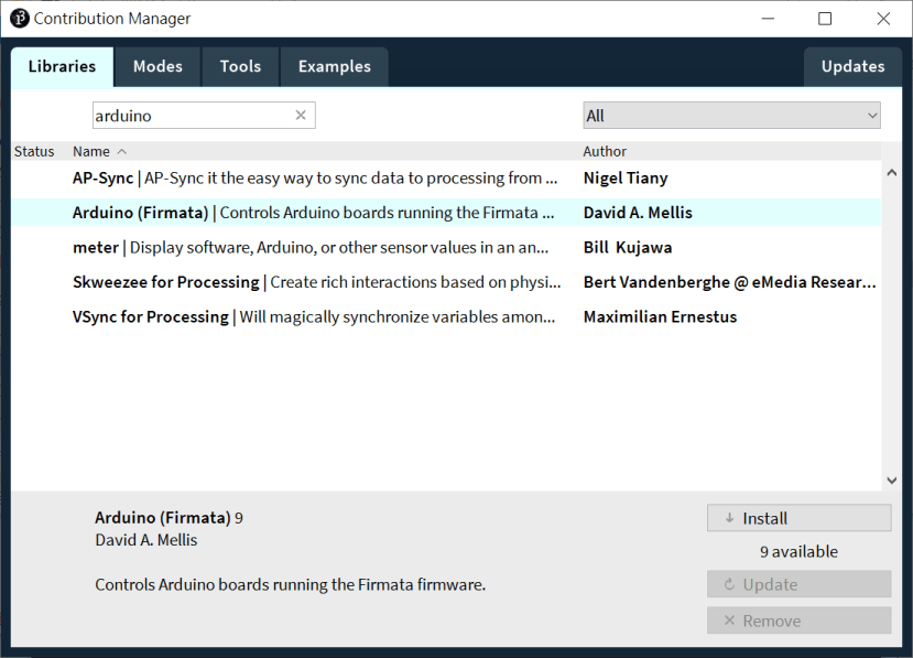
開啟 Processing IDE,點選 Sketch → Import Library → Add Library,開啟 Contribution Manager 視窗,並搜尋 arduino。點選 Arduino (Firmata) 再點選 Install,就會開始安裝,如下圖:
也會帶入對應的範例,只要是另外安裝的函式庫範例都會為在 Contributed Libraries 下。一共有五個範例,今天會說明其中的:
- arduino_input:把 Arduino 腳位狀態呈現在 Processing 中
- arduino_output:在 Processing 中點選畫面來控制 Arduino 腳位狀態 (數位)
arduino_pwm:在 Processing 中移動滑鼠來控制 Arduino 腳位狀態 (類比)

執行 arduino_input 範例
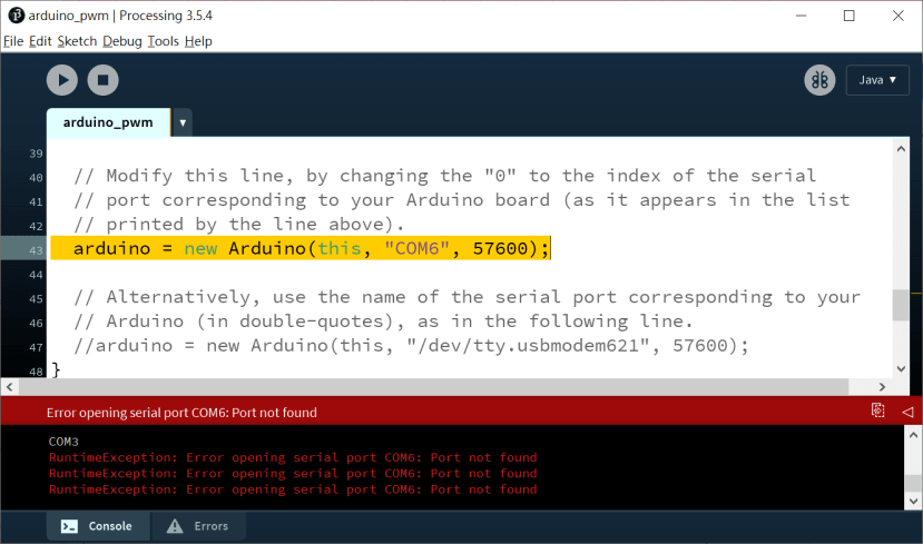
請直接開啟 arduino_input 範例,這個範例屬於輸位輸入與類比輸入。請確認您的 Arduino 板子正在執行 StandardFirmata 程式,您可以重新插拔電源或按一下 Arduino 板子上的 Reset 按鈕讓它重新啟動程式。總之,當您按下 Processing 的 Run 按鍵時,Arduino 必須先執行程式才行,否則會出現 RuntimeException: Error opening serial port COM6: Port not found 這樣的錯誤訊息。
一切順利的話,會看到下方的畫面,上方的方塊代表 Arduino Uno 的 D0 - D13 數位輸入/輸出腳位,您可以在任一個腳位接上按鈕,按下按鈕就會使對應腳位的方塊變成淺色。而下方的圓圈則代表 Arduino Uno 的 A0 - A6 的類比輸入腳位。


重要指令說明如下:
- import cc.arduino.*; --> 匯入 arduino 函式庫
- Arduino arduino; --> 宣告一個 arduino 物件,如果您的專題需要連接多片 arduino 的話,就需要宣告多個 arduino 物件
- println(Arduino.list()); -->列出可用的 COM port 裝置
- arduino = new Arduino(this, Arduino.list()[0], 57600);--> 設定這個 arduino 物件的 COM port 位置與傳輸速率。list()[0] 代表第一個 arduino,或者您可以改用 “COMX” 來指定位置
- pinMode(i, Arduino.INPUT); → 設定指定腳位為輸入模式
- digitalRead(i) -> 讀取數位腳位狀態,也就是 arduino UNO 的 D0 - D13 腳位
- analogRead(i) → 讀取類比腳位狀態,也就是 arduino UNO 的 A0 - A5 腳位
arduino_input 完整程式碼如下,為避免占版面已刪除註解,請自行開啟 Processing 來看註解:
import processing.serial.*;

import cc.arduino.*;

Arduino arduino;

color off = color(4, 79, 111);
color on = color(84, 145, 158);

void setup() {
  size(470, 280);
  println(Arduino.list());
  arduino = new Arduino(this, Arduino.list()[0], 57600);

  for (int i = 0; i <= 13; i++)
    arduino.pinMode(i, Arduino.INPUT);
}

void draw() {
  background(off);
  stroke(on);

  for (int i = 0; i <= 13; i++) {
    if (arduino.digitalRead(i) == Arduino.HIGH)
      fill(on);
    else
      fill(off);

    rect(420 - i * 30, 30, 20, 20);
  }

  noFill();
  for (int i = 0; i <= 5; i++) {
    ellipse(280 + i * 30, 240, arduino.analogRead(i) / 16, arduino.analogRead(i) / 16);
  }
}
執行 arduino_out 範例
這個範例屬於數位輸出,點選畫面上端的方塊就可以改變該方塊的顏色,並讓 Arduino 對應的腳位為高電位,如果該腳位接一個 LED 的話,就會亮起,再點一次則熄滅。執行畫面如下:

重要指令說明如下:
- pinMode(i, Arduino.OUTPUT);; → 設定指定腳位為輸出模式
- for (int i = 0; i <= 13; i++) { if (values[i] == Arduino.HIGH)... → 根據 value[] 陣列的內容來決定畫面上端方塊的顏色
- digitalWrite(pin, Arduino.HIGH); → 寫入數位腳位狀態,HIGH 為高電位,如果該腳位接一個 LED 的話,就會亮起。反之 LOW 則是低電位(LED熄滅)
arduino_output 完整程式碼如下,為避免占版面已刪除註解,請自行開啟 Processing 來看註解:
import processing.serial.*;
import cc.arduino.*;
Arduino arduino;

color off = color(4, 79, 111);
color on = color(84, 145, 158);

int[] values = { Arduino.LOW, Arduino.LOW, Arduino.LOW, Arduino.LOW,
 Arduino.LOW, Arduino.LOW, Arduino.LOW, Arduino.LOW, Arduino.LOW,
 Arduino.LOW, Arduino.LOW, Arduino.LOW, Arduino.LOW, Arduino.LOW };

void setup() {
  size(470, 200);
  println(Arduino.list());
  arduino = new Arduino(this, Arduino.list()[0], 57600);
  for (int i = 0; i <= 13; i++)
    arduino.pinMode(i, Arduino.OUTPUT);
}

void draw() {
  background(off);
  stroke(on);

  for (int i = 0; i <= 13; i++) {
    if (values[i] == Arduino.HIGH)
      fill(on);
    else
      fill(off);

    rect(420 - i * 30, 30, 20, 20);
  }
}

void mousePressed()
{
  int pin = (450 - mouseX) / 30;

  if (values[pin] == Arduino.LOW) {
    arduino.digitalWrite(pin, Arduino.HIGH);
    values[pin] = Arduino.HIGH;
  } else {
    arduino.digitalWrite(pin, Arduino.LOW);
    values[pin] = Arduino.LOW;
  }
}
執行 arduino_pwm 範例
本範例為類比寫入,把 Processing 視窗上滑鼠的 X 座標轉換為 Arduino PWM 可接受的數值範圍 (0-255)。如果您根據程式說明,在 D9 與 D11 各接一個 LED 的話,當滑鼠慢慢往右移動時,9號LED會慢慢變亮,11號則是慢慢變亮。但當滑鼠往左時,兩個 LED 的亮暗情況就相反了。
其實這個範例與 arduino_servo 可說是完全相同,差別只在於前者是用 arduino.analogWrite() 指令,後者則是用 arduino.servoWrite() 指令來控制伺服機的角度。
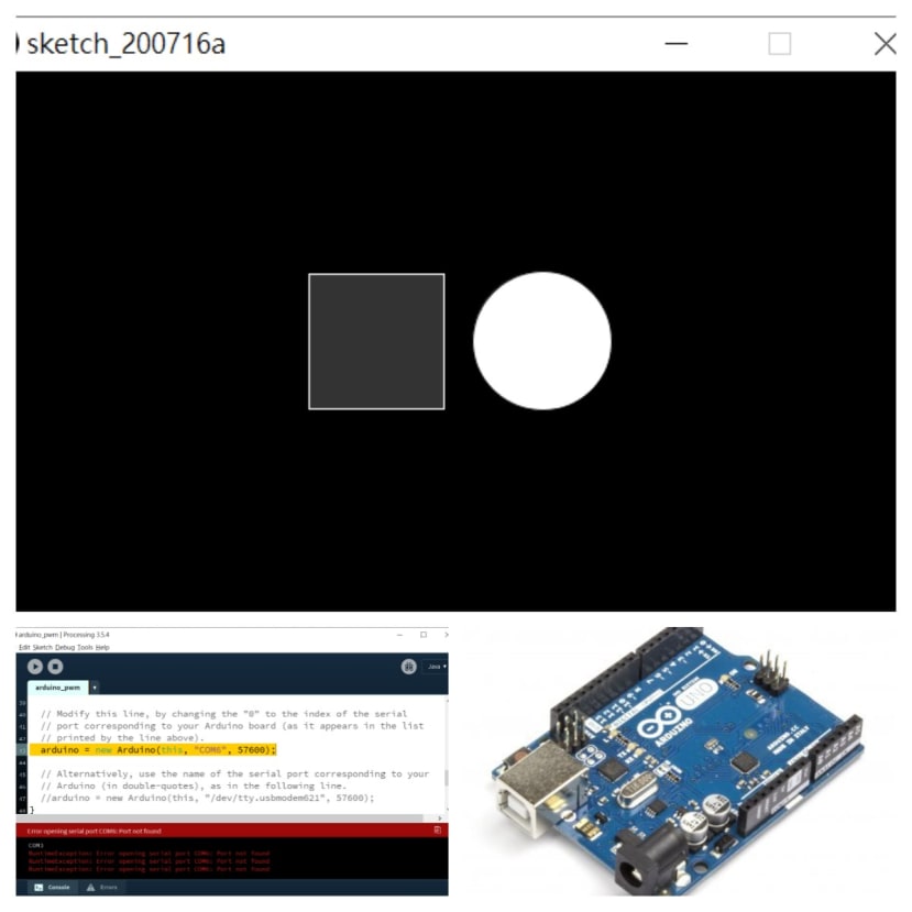
執行畫面如下,滑鼠愈靠近視窗左邊,畫面愈黑,反之往右則漸漸變為白色:


重要指令說明如下:
- analogWrite(9, constrain(mouseX / 2, 0, 255)); → 取得滑鼠的 X 座標 (mouseX) 並限制範圍在 0 -255 之間,用來控制 9 號 LED 的亮度
- analogWrite(11, constrain(255 - mouseX / 2, 0, 255)); → 與上一步差不多,但 255 - mouseX 是用來反向控制 LED 亮度。
arduino_pwm 完整程式碼如下,為避免占版面已刪除註解,請自行開啟 Processing 來看註解:
import processing.serial.*;

import cc.arduino.*;

Arduino arduino;

void setup() {
  size(512, 200);

  println(Arduino.list());
  arduino = new Arduino(this, "COM6", 57600);
}

void draw() {
  background(constrain(mouseX / 2, 0, 255));

  arduino.analogWrite(9, constrain(mouseX / 2, 0, 255));
  arduino.analogWrite(11, constrain(255 - mouseX / 2, 0, 255));
}
透過 USB 傳訊號
如果您要接收數位感測器(例如 DHT 11 溫溼度感測器或加速度計),Processing 的 Arduino 函式庫就做不到啦,因為它只支援基本的數位類比 I/O 而已,這時候應該怎麼辦呢?這時候就需要自己定義要收發哪些資料。請看以下說明:
Processing 端
基本的概念就是一個蘿蔔一個坑,Processing 發送什麼,Arduino 端就會根據收到的東西來做事情。這邊的重點就是兩邊一定要對應,否則就會郵差總是按錯鈴啦!影片連結:https://www.youtube.com/watch?v=_EgFOG1MyEk
這裡會用到 Processing 的 Serial 函式庫,請根據先前步驟安裝完成即可。執行畫面如下,按下畫面的方形與圓形區域(請把他們當成按鈕),畫面會變色,且會送出字元 ‘A’ (方形)與 ‘B’ ()給 7697,7697 則根據接受到的指令來做事。請注意 serial 序列傳輸基本的概念就是先發送的資料會先抵達(不考慮掉封包的情況),就好像排隊一樣,同時間只會接收到一筆資料,所以 Arduino 端只要用 if 或 switch 來依序處理即可,相當簡單。


重要的指令說明如下:
- myPort = new Serial(this, Serial.list()[0], 9600); 建立一個新的序列通訊物件,用法與之前的 arduino 物件相當類似
- while (myPort.available() > 0) → 如果 myPort 有接收到資料,代表 Arduino 端有資料傳過來
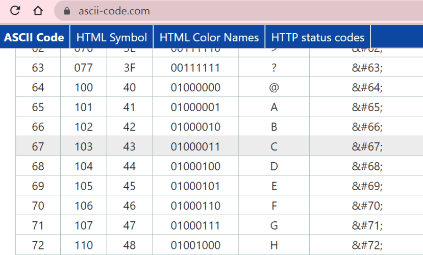
- int inByte = myPort.read(); 讀取接收到的資料,並存入 inByte 整數變數中。您可能會好奇 Arduino 不是送一個字元 'C' 嗎?為什麼要用整數呢?原因在於序列通訊最基礎的型態是 ASCII 編碼,https://www.ascii-code.com/
- if (inByte == 'C') → 如果收到內容的 ASCII 編碼為 C 也就是 67,對應編碼如下圖:
- write('A'); → 送出字元A,別忘了它的 ASCII 編碼實際上是 65
Processing 端完整程式碼如下:
import processing.serial.*;

int rectX, rectY;      // Position of square button
int circleX, circleY;  // Position of circle button
int rectSize = 90;     // Diameter of rect
int circleSize = 93;   // Diameter of circle
color rectColor, circleColor, baseColor;
color rectHighlight, circleHighlight;
color currentColor;
boolean rectOver = false;
boolean circleOver = false;

int bg=0;

Serial myPort;

void setup() {

  myPort = new Serial(this, Serial.list()[0], 9600);
  size(640, 360);
  rectColor = color(0);
  rectHighlight = color(51);
  circleColor = color(255);
  circleHighlight = color(204);
  baseColor = color(102);
  currentColor = baseColor;
  circleX = width/2+circleSize/2+10;
  circleY = height/2;
  rectX = width/2-rectSize-10;
  rectY = height/2-rectSize/2;
  ellipseMode(CENTER);
}

void draw() {
  update(mouseX, mouseY);
  while (myPort.available() > 0) {
    int inByte = myPort.read();
    if (inByte == 'C') {
      bg++;
      if (bg>1) bg=0;
      if (bg==1) currentColor=color(0,255,0);
      if (bg==0) currentColor=color(255,0,0);
    }
  }

  background(currentColor);

  if (rectOver) {
    fill(rectHighlight);
  } else {
    fill(rectColor);
  }
  stroke(255);
  rect(rectX, rectY, rectSize, rectSize);

  if (circleOver) {
    fill(circleHighlight);
  } else {
    fill(circleColor);
  }
  stroke(0);
  ellipse(circleX, circleY, circleSize, circleSize);
}

void update(int x, int y) {
  if ( overCircle(circleX, circleY, circleSize) ) {
    circleOver = true;
    rectOver = false;
  } else if ( overRect(rectX, rectY, rectSize, rectSize) ) {
    rectOver = true;
    circleOver = false;
  } else {
    circleOver = rectOver = false;
  }
}

void mousePressed() {
  if (circleOver) {
    currentColor = circleColor;
    myPort.write('A');  //送出字元A
  }
  if (rectOver) {
    currentColor = rectColor;
    myPort.write('B');  //送出字元B
  }
}

boolean overRect(int x, int y, int width, int height)  {
  if (mouseX >= x && mouseX <= x+width &&
      mouseY >= y && mouseY <= y+height) {
    return true;
  } else {
    return false;
  }
}

boolean overCircle(int x, int y, int diameter) {
  float disX = x - mouseX;
  float disY = y - mouseY;
  if (sqrt(sq(disX) + sq(disY)) < diameter/2 ) {
    return true;
  } else {
    return false;
  }
}
Arduino端
Arduino 端程式較為簡單,重要指令說明如下:
- begin(9600); → 啟動序列通訊,通訊速率為 9600,請注意這時不可開啟 Arduino IDE 的 Serial Monitor,否則 Processing 會因為 COM port 被占用而無法連線
- if (Serial.available()) { → 如果 Serial 有接收到資料,代表 Processing 端有資料傳過來
- char code = Serial.read(); → 將序列埠接收到的資料存在字元變數 code 中
- if (code == 'A') → 判斷 code 值並執行對應的動作(控制兩顆LED)
- print('C'); → 透過序列埠送出字元 C
void setup()
{
  Serial.begin(9600);
  pinMode(3,INPUT);
  pinMode(4,OUTPUT);
  pinMode(5,OUTPUT);
  digitalWrite(4,LOW);
  digitalWrite(5,LOW);
}

void loop()
{
  if (Serial.available()) {
    char code = Serial.read();
    if (code == 'A') {
      digitalWrite(4,HIGH);
      digitalWrite(5,LOW);
    }
    if (code == 'B') {
      digitalWrite(4,LOW);
      digitalWrite(5,HIGH);
    }
  }

  if (digitalRead(3)==LOW) {  //如果#3按鈕被按下,送字元 C 給 Processing
    Serial.print('C');
    delay(200);
  }
}
想想看
本篇文章介紹了兩種 Processing 與 Arduino Uno 這類簡易開發板的互動方式,想想看,還有哪些有趣的控制方式呢?