
入门
了解如何下载、安装和登录软件
使用我们为初级、中级和高级工程师提供的分步教程,在从设计到制造的过程中先发制人
了解如何下载、安装和登录软件
学习如何浏览和使用软件内的功能
"我们的如何操作指南可以帮助您构建您的第一个可打印设计 "

了解 3D 模型以及如何使用它们
使用软件内的功能来完成您的项目

准备您的 3D 项目设计,以便打印它
寻找灵感,获得支持,并与其他 DesignSpark Mechanical 创作者分享您的作品。
手書きで書いた線上に添付ファイルのような台形形状を乗せて加工したいと考えています。線幅と同じように加工するにはどうしたらよいでしょうか?I want to process handwritten lines by adding a trapezoidal shape like the attached file.
How can I process it in the same way as the line width?thank you. I was working on something and suddenly I got an error, it said something about graphics, it asked me to save before closing and when I reopened it I tried to open the file again, it seems to want to open it but I get a message saying "the document cannot be opened" what can I do in this case, the document seems to be fine but I can't open it. Schreiben Sie einen eigenen Beitrag auf DesignSpark!
DesignSpark hat über 1,4 Millionen Mitglieder und wird jedes Jahr von mehr als 5 Millionen Besuchern aufgerufen. Die Inhalte auf DesignSpark werden von unserer wunderbaren Gemeinschaft von Technikern, Studierenden und Lieferanten erstellt.
Wenn Sie einen Beitrag verfassen oder mit anderen Mitgliedern interagieren möchten, finden Sie nachstehend den entsprechenden Link
https://www.rs-online.com/designspark/writing-content-on-DesignSpark-de
I am unable to log in due to a License Error.
What should I do?
My friend has a problem with instalation Designspark mechanical ver 6.0.3 (2023 R1) 64-bit. On my computer was instalation O.K., but the same instalation file on his PC during instalation give error 1001 (picture in addendum). His machine is i5 with Windows11 home 64-bit. Can you help, please? Thank you, ZdendaS Czech Republic DesignSpark features over 14,000 pieces of content on many varied subjects ad all written by our community of engineers, students and our suppliers.
Take a look at our Technology based content in All Technologies, our student created content in Student Content or why not browse our trending content in Also In The News.
Why not add some content yourself and have access to over 5 million site visitors per year, click the link below
https://www.rs-online.com/designspark/writing-content-on-DesignSpark
I've attempted to "paint" and texture the surface of models from DSM in programs like Substance Painter, but the UV map of the model is nonsensical AND it tends to crash whatever program I am using. Can someone at RS explain what is going on and why this is happening? 账户和密码确认是正确的,因为我可以登录官网,但是打开软件登录时一直提示“DesignSpark Mechanical在注册过程中发生错误。” hab mir jetzt die neuste version runtergeladen , kann mich aber nicht mehr an melden...mit e mail nicht oder benutzername , pw stimmt ...
iwas down oder keine free linzens mehr?
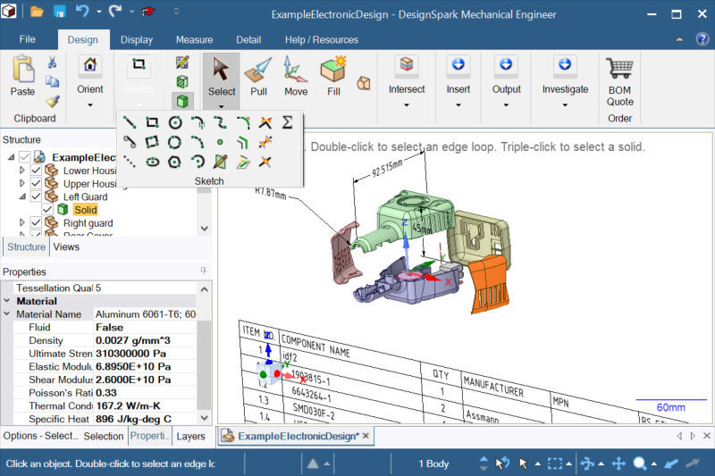
danke für die hilfe We are creating an original 2D drawing template and want to automatically transcribe component names and control numbers into the drawing frame from the 3D data’s component properties. Is it possible to create components with preset component properties to link the component properties and the drawing frame?
オリジナルの2D図面のテンプレートを作成しており、図枠に部品名称や管理番号を、3Dデータのコンポーネントプロパティーから自動転記できるようにしたいです。コンポーネントプロパティーと図枠をリンクさせるために、あらかじめ決めておいたコンポーネントプロパティーをプリセットした状態でコンポーネントを作成できるようにしたいのですが、このような設定は可能なのでしょうか? Dear sir.Recently, I have been unable to perform the following operations.
This is an operation that was previously possible.
1.By selecting and pressing the side of the solid, I was able to add rounded corners.
Currently, when I select an edge, I don't see an arrow to push it.
2.Similarly , if you wanted to select a face to a solid, previously you could just press the face.
There are currently two types of operations: solids thah can do this , and cases that always create different solids.
Is this a configuration issue or has the UI changed ??
please give me some advice. bei mir kommt immer dieselbe Fehlermeldung, wenn ich versuche alte dateien die ich mit Designspark erstellt habe zu öffnen?
Woher kommt dieses Problem und gibt es eine Lösung dafür?
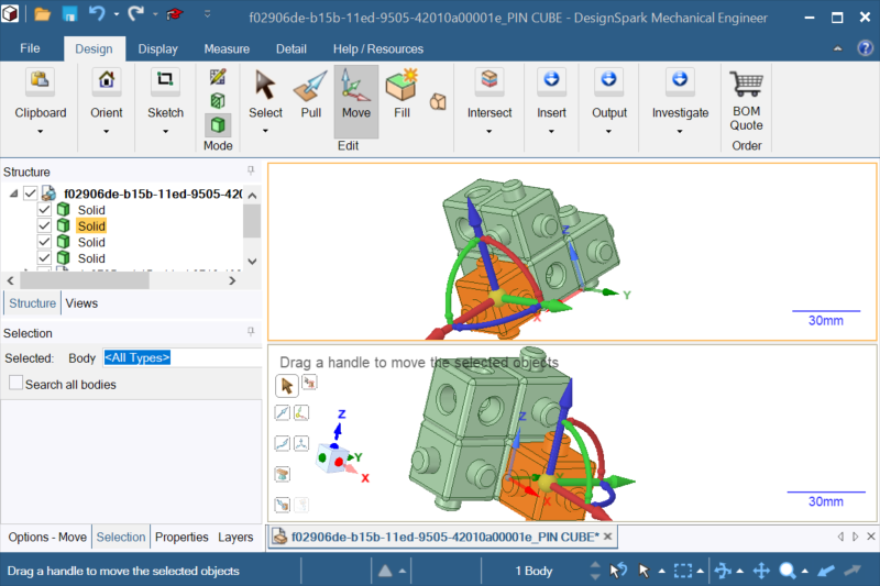
I need to be able to skew a drawing as per the attached simplified picture. I have only been able to do this with cylinders so far but as for complex objects, so far no luck.
Essentially the uppermost face and lower most face remain parallel as per the left hand image. The rest of the image will tilt by the desired number of degrees.
Cheers.
A typical way of working is to copy an assembly as a new assembly. Open that assembly and modify it to suit the new design. I always save as "overwrite any modified external documents". If I do need a specifc new part I will create a new one.
I notice something odd, if I triple click a component in the assembly and delete it, it's deleted it from every assembly it appears in. If I delete the component from the structure tree it only deletes it from the assembly I am in. If in select I use the dropdown and check compontents, select the component and delete it but only in the assembly I am in.
So if I triple click it selects the part not the component and when I delete deletes the sold within the components, but as I'm in an assembly this makes no sense. Unfortunatly I have now "destroyed" several components that no longer have a part within.
Can anyone explain the logic here ?
How can I toggle quickly the select mode (part or compontent)
As a workaround I am using "move" to delete as in that command the selection of the part or component is on screen
Thanks
Adding to this, 99% of the time , especially in an assembly I want to select component not the body, even if I check the select component it defaults back to body (or face etc) . I've put a shortcut in the quick access toolbar but honestly I keep forgetting to change to component as it keep changing back to the mode I dont want. Realistically this is destroying productivity and I have now lost several components. I may have to look into other software options. DXFファイルインポート後,線がすべてArcになりプルもできません。
ボイントで線上に配置後、スプラインで上側をなぞってプルするようにしていますが
すべてがdxf上に線を引くことができません
一括選択して簡単にプルや線種変更はできないでしょうか?
手書き線の加工 Processing handwritten lines
Can`t open a file
Sie haben ein Projekt? Wir freuen uns über Ihren Blogbeitrag
License Error - Bad Request
Error 1001 during Instalation DSM ver 6.0.3
Write about your own project or design
Can't Add Textures to Exported DSM files like OBJ
无法登录
kann mich nicht mehr anmelden?
How to create components with arbitrary custom document property information
Select Solid's side and operations
fehler beim laden der körpergeometrie
Skew or shear an object
Copy assembly problems
DXFファイルインポート後の線処理について