 戴夫来自 DesignSpark
How do you feel about this tutorial? Help us to provide better content for you.
戴夫来自 DesignSpark
Thank you! Your feedback has been received.
戴夫来自 DesignSpark
There was a problem submitting your feedback, please try again later.
戴夫来自 DesignSpark
What do you think of this tutorial?
本教程需要:
DesignSpark PCB V11.0.0原理图符号的大小没有限制,但它应与其他符号的大小相匹配,以在原理图设计中实现统一。
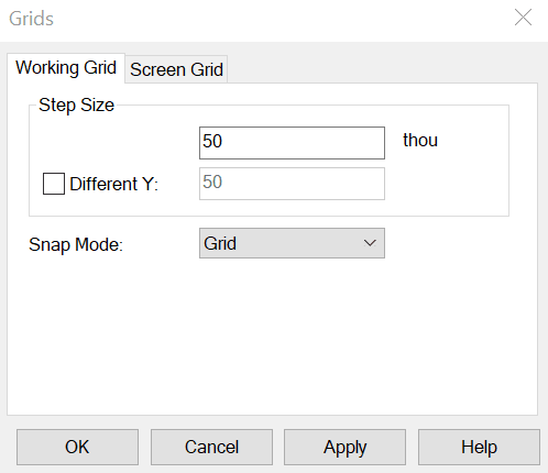
默认的技术文件使用 5 万网格。
PPL の標準シンボルの一部について、それぞれの長さと幅を以下に示します。
コンポーネント回路図のシンボル作成に使用されるスタイルは、以下になります (デザインテクノロジーで表示可)。
ラインスタイル [pin] 、線の幅は 6 です。
ラインスタイル [thin] 、線の幅は 10 です。
テキストスタイル[デフォルト] 、幅が 50、線の幅は 5 で 「システムストロークフォント」 を使用しています。
これらの詳細をガイドとして使用すると、回路図の一貫したシンボルを作成することができます。