Processing數位互動介面開發軟體應用- Processing 影像應用與 openCV 人臉追蹤
关注文章
 戴夫来自 DesignSpark
你觉得这篇文章怎么样? 帮助我们为您提供更好的内容。
戴夫来自 DesignSpark
Thank you! Your feedback has been received.
戴夫来自 DesignSpark
There was a problem submitting your feedback, please try again later.
戴夫来自 DesignSpark
你觉得这篇文章怎么样?
|
作者 |
曾吉弘 |
|
難度 |
普通 |
|
材料表 |
1. Arduino UNO
|

本文要介紹如何在 Processing IDE 中匯入OpenCV視覺函式庫,目標是做出一個可以上下左右追蹤臉孔的相機雲台。
在 Processing 中使用這比建置完整的OpenCV環境做法簡單多了,但是功能相對也會比完整的 openCV 環境來得少,就看您個人的需求囉。Processing opencv 相較於最新的 opencv 4.0 當然是舊了很多,但 Processing 的程式碼都很簡潔,很容易做出漂亮的介面,要結合Arduino也很簡單,絕對值得您試試看喔。
更多資訊請直接慘考 Processing openCV 函式庫的 github:https://github.com/atduskgreg/opencv-processing
硬體
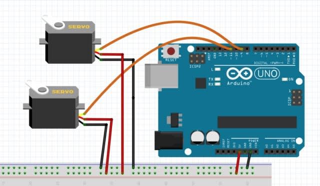
Arduino 與 Processing 的連線設定請參考上一篇的教學,所需的硬體如材料表。
請將#1伺服機的訊號腳位接到Arduino的#9腳位,用於控制PTZ平台的水平方向移動(Pan)
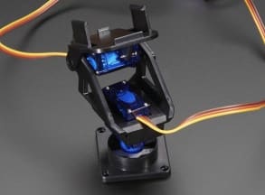
請將#2伺服機的訊號腳位接到Arduino的#11腳位,用於控制PTZ平台的垂直方向移動(Tilt)。其餘分別接電接地完成即可。最後在頂端接上您的 webcam,但注意平台會轉動,因此所有線材都要預留一定的長度。您可由 thingiverse 這樣的網站找到更多的PTZ平台設計

Processing設定
1.請開啟 Processing 官方網站的下載頁面,根據您所使用的硬體平台下載對應的版本,如果還沒下載請參考上一篇文章。
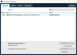
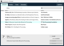
開啟 Processing IDE,點選 Sketch → Import Library → Add Library,開啟 Contribution Manager 視窗,分別安裝好以下兩個函式庫:,如下圖:
2.完成之後 File → Examples 看到相關範例,都可以直接玩玩看喔

說真的,Processing的 Pimage 與 video 套件已經能做出相當不錯的效果,先來看看兩個範例,關鍵就是在於您想要怎樣的效果還有自身創意囉!
馬賽克效果
本範例來自 Daniel shiffman 的 Learning Processing 一書範例(http://learningprocessing.com/examples/chp16/example-16-08-BrightnessMirror)。會把畫面切成多個方塊,每個方塊的大小會根據該區域的亮度來決定。亮度愈亮,方塊愈大,反之則愈小。先說喔,這個範例沒有用到 opencv,只是單純的馬賽克效果而已。先看一下執行效果:
插入影片 01.mp4 (RS影音串流平台連結)

重要指令說明如下:
- int videoScale = 10; → 這個變數值會決定畫面的馬賽克程度
- cols = width / videoScale; → 根據 videoScale變數值來切分畫面的行數
- rows = height / videoScale; → 根據 videoScale變數值來切分畫面的列數
- loadPixels(); → 載入所有像素以便後續處理
- for (int i = 0; i < cols; i++) { for (int j = 0; j < rows; j++) { → 掃過畫面所有的行列,就是整個畫面
- int loc = (video.width - i - 1) + j * video.width; → 所有欄反向排列,來將影像鏡像
- color c = video.pixels[loc]; → 取得指定位置像素之顏色值,每個方塊的大小與其中所有像素的亮度成比例。愈亮方塊愈大,反之則愈小
- float sz = (brightness(c)/255) * videoScale; → 使用 brightness() 語法取得 c 點之亮度,再乘上 videoScale 變數值來算出最終的方塊寬度與高度
完整程式碼如下,為避免占版面已刪除註解,請自行開啟上述連結來看註解:
// Each pixel from the video source is drawn as
// a rectangle with size based on brightness.

import processing.video.*;
int videoScale = 10;
int cols, rows;
Capture video;

void setup() {
  size(640, 480);
  cols = width / videoScale;
  rows = height / videoScale;
  video = new Capture(this, cols, rows);
  video.start();
}

void captureEvent(Capture video) {
  video.read();
}

void draw() {
  background(0);
  video.loadPixels();
  for (int i = 0; i < cols; i++) {
    for (int j = 0; j < rows; j++) {
      int x = i*videoScale;
      int y = j*videoScale;

      int loc = (video.width - i - 1) + j * video.width;

      color c = video.pixels[loc];
      float sz = (brightness(c)/255) * videoScale;

      rectMode(CENTER);
      fill(255);
      noStroke();
      rect(x + videoScale/2, y + videoScale/2, sz, sz);
    }
  }
}
動作偵測
本範例來自 Daniel shiffman 的 Learning Processing 一書範例(http://learningprocessing.com/examples/chp16/example-16-13-MotionPixels),會比較兩個 frame 之間的差異,並把畫面中移動(差異大於一定程度)的地方顯示出來。您後續可以調整差異下限(請看以下說明) 或前後景顏色來產生更多有趣的效果。先看一下執行效果:

插入影片 02.mp4 (RS影音串流平台連結)
重要指令說明如下:
- float threshold = 50; → 像素被判斷為移動像素的下限,您可修改這個值來調整程式的敏感度
- copy(video, 0, 0, video.width, video.height, 0, 0, video.width, video.height); 把前一個 frame 存起來偵測動作。在讀取新的 frame 之前,一定要先把原本的 frame 存起來才能進行比較
- loadPixels(); prevFrame.loadPixels(); → 載入現在與前一個 frame 的所有像素
- for (int x = 0; x < video.width; x ++ ) { for (int y = 0; y < video.height; y ++ ) { → 同上一個範例,用兩個 for loop 來刷過所有像素來進行比較
- int loc = x + y*video.width; → 計算 1D 像素位置
- color current = video.pixels[loc]; → 計算這個像素的顏色,請參考 Processing 的 color() 函式
- color previous = prevFrame.pixels[loc]; → 計算上一張 frame中,同一個位置之像素顏色
- float diff = dist(r1, g1, b1, r2, g2, b2); → 比較這兩個點的顏色差,使用 dist() 距離函數來計算兩個 frame 中同一點的顏色差,float r1, g1, b1 為 prevFame 的該點像素顏色, float r2, g2, b2 為 currentFame 的該點像素顏色
- if (diff > threshold) { → 如果該像素的顏色差大於所設定的值(50)
- pixels[loc] = color(0); → 代表發生動作,該點設為黑色
- else { pixels[loc] = color(255); → 反之設為白色
完整程式碼如下,為避免占版面已刪除註解,請自行開啟上述連結來看註解:
import processing.video.*;
Capture video;
PImage prevFrame;
float threshold = 50;

void setup() {
  size(320, 240);
  video = new Capture(this, width, height, 30);
  video.start();
  prevFrame = createImage(video.width, video.height, RGB);
}

void captureEvent(Capture video) {
  prevFrame.copy(video, 0, 0, video.width, video.height, 0, 0, video.width, video.height);
  prevFrame.updatePixels();
  video.read();
}

void draw() {

  loadPixels();
  video.loadPixels();
  prevFrame.loadPixels();

  for (int x = 0; x < video.width; x ++ ) {
    for (int y = 0; y < video.height; y ++ ) {

      int loc = x + y*video.width;
      color current = video.pixels[loc];
      color previous = prevFrame.pixels[loc];

      float r1 = red(current);
      float g1 = green(current);
      float b1 = blue(current);
      float r2 = red(previous);
      float g2 = green(previous);
      float b2 = blue(previous);
      float diff = dist(r1, g1, b1, r2, g2, b2);

      if (diff > threshold) {
        pixels[loc] = color(0);
      } else {
        pixels[loc] = color(255);
      }
    }
  }
  updatePixels();
}
邊緣偵測
好了,那來看看 openCV 的範例吧。 在諸多影像處理技術中,邊緣偵測是相當重要的演算法之一,因為先找到邊緣才能進一步把一個物體的輪廓抓出來,並根據這個輪廓在畫面中的位置來算出它的移動方向、距離等等。
這邊用到的 canny, scharr sobel 分別代表不同的邊緣偵測演算法 請在 .pde 程式檔的同一個目錄下放一張您想要進行邊緣偵測的圖片,再執行程式就可以看到如下的畫面:
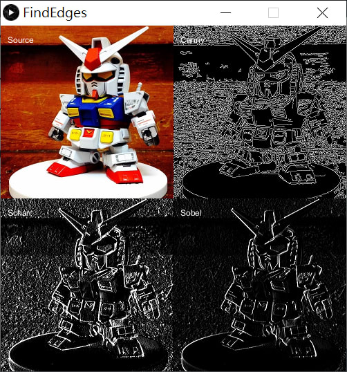
重要指令說明如下:
- src = loadImage("toy.jpg"); → 載入圖片
- findCannyEdges(20,75); → 使用 Canny 邊緣偵測演算法來偵測邊緣,(20, 75) 代表上下限,詳情請參考 http://atduskgreg.github.io/opencv-processing/reference/gab/opencv/OpenCV.html
- canny = opencv.getSnapshot(); → 取得辨識結果快照
- image(src, 0, 0);
- image(canny, src.width, 0);
- image(scharr, 0, src.height);
- image(sobel, src.width, src.height); -> 這四段把不同的邊緣偵測演算法結果顯示在同一個 image 上,請仔細看看如何指定其位置
完整程式碼如下,為避免占版面已刪除註解,請自行開啟上述連結來看註解
import gab.opencv.*;

OpenCV opencv;
PImage src, canny, scharr, sobel;

void setup() {
  src = loadImage("toy.jpg");
  size(1080, 720);

  opencv = new OpenCV(this, src);
  opencv.findCannyEdges(20,75);
  canny = opencv.getSnapshot();

  opencv.loadImage(src);
  opencv.findScharrEdges(OpenCV.HORIZONTAL);
  scharr = opencv.getSnapshot();

  opencv.loadImage(src);
  opencv.findSobelEdges(1,0);
  sobel = opencv.getSnapshot();
}

void draw() {
  pushMatrix();
  scale(0.5);
  image(src, 0, 0);
  image(canny, src.width, 0);
  image(scharr, 0, src.height);
  image(sobel, src.width, src.height);
  popMatrix();

  text("Source", 10, 25);
  text("Canny", src.width/2 + 10, 25);
  text("Scharr", 10, src.height/2 + 25);
  text("Sobel", src.width/2 + 10, src.height/2 + 25);
}
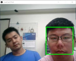
人臉追蹤
開啟範例程式:LiveCamTest,可以直接追蹤臉孔囉,以下程式碼已經加入 Arduino 相關控制碼,但您需要根據實際情況來調整伺服機的角度,不然有可能會讓它轉過頭而壞掉喔。
插入影片 03.mp4 (RS影音串流平台連結)
執行畫面如下,可以看到畫面會把偵測到的臉孔標出來,也會在console中顯示偵測到的臉孔張數與座標。由於在此的臉孔辨識是採用Haar分類演算法,所以當您左右轉動臉或是把臉傾斜一個角度之後,系統就無法辨識你的臉了

重要指令說明如下:
- loadCascade(OpenCV.CASCADE_FRONTALFACE); → 使用代表在此的臉孔追蹤還是用到了Haar分類演算法,點選連結可以看到關於本分類法的數理基礎。
- loadImage(video); → 載入即時畫面
- Rectangle[] faces = opencv.detect(); //偵測是否有臉
- for (int i = 0; i < faces.length; i++) { //根據臉孔數目來跑迴圈
- println(faces[i].x + "," + faces[i].y); //顯示臉的座標
- rect(faces[i].x, faces[i].y, faces[i].width, faces[i].height); //畫長方形把臉框出來
- center_x = faces[i].x + (faces[i].width/2); //起始點x + 0.5*寬
- center_y = faces[i].y + (faces[i].height /2); //起始點y + 0.5*高
- ellipse(center_x, center_y, 10, 10); → 在偵測到的臉部中心畫一個圓
- face_x = faces[0].x + (faces[i].width/2); → 取得第一張臉的中心x座標
- face_y = faces[0].y + (faces[i].height/2); → 取得第一張臉的中心y座標
- servoWrite(9, int(map(center_x, 100, 270, 0, 180))); → 根據臉孔
- servoWrite(11, int(map(center_y, 80, 250, 0, 180)));
import gab.opencv.*;
import processing.video.*;
import java.awt.*;
import processing.serial.*;
import cc.arduino.*;

int center_x, center_y;
Arduino arduino;

Capture video;
OpenCV opencv;

void setup() {
  size(640, 480);
  video = new Capture(this, 640/2, 480/2);
  opencv = new OpenCV(this, 640/2, 480/2);
  opencv.loadCascade(OpenCV.CASCADE_FRONTALFACE);
  println(Arduino.list());

  arduino = new Arduino(this, Arduino.list()[0], 57600);
  //0代表第一個COM裝置,請根據實際狀況修改
  arduino.pinMode(9, Arduino.SERVO);     //#1 servo 水平
  arduino.pinMode(11, Arduino.SERVO);   //#2 servo 垂直
  video.start();
}

void draw() {
  scale(2);
  opencv.loadImage(video);

  image(video, 0, 0 );

  noFill();
  stroke(0, 255, 0);
  strokeWeight(2);
  Rectangle[] faces = opencv.detect();   //偵測是否有臉
  println(faces.length);                            //偵測到幾張臉

  for (int i = 0; i < faces.length; i++) {    //根據臉孔數目來跑迴圈
    println(faces[i].x + "," + faces[i].y);    //顯示臉的座標
    rect(faces[i].x, faces[i].y, faces[i].width, faces[i].height); //畫長方形把臉框出來
    center_x = faces[i].x + (faces[i].width/2);   //起始點x + 0.5*寬
    center_y = faces[i].y + (faces[i].height /2);  //起始點y + 0.5*高
    print(center_x);
    print(", ");
    println(center_y);
    ellipse(center_x, center_y, 10, 10);

    face_x = faces[0].x + (faces[i].width/2);
    face_y = faces[0].y + (faces[i].height/2);
    arduino.servoWrite(9, int(map(face_x, 100, 270, 0, 180)));
    arduino.servoWrite(11, int(map(face_y, 80, 250, 0, 180)));
  }

  delay(100);
}

void captureEvent(Capture c) {
  c.read();
}
執行
由 Processing console 的訊息可以看到以下訊息:
OpenCV for Processing 0.5.4 by Greg Borenstein http://gregborenstein.com

Using Java OpenCV 2.4.5.0

Load cascade from: C:/Users/user/Documents/Processing/libraries/opencv_processing/library/cascade-files/haarcascade_frontalface_alt.xml

Cascade loaded: haarcascade_frontalface_alt.xml