如何以 DXF 导入电路板轮廓?
关注教程
 戴夫来自 DesignSpark
How do you feel about this tutorial? Help us to provide better content for you.
戴夫来自 DesignSpark
Thank you! Your feedback has been received.
戴夫来自 DesignSpark
There was a problem submitting your feedback, please try again later.
戴夫来自 DesignSpark
What do you think of this tutorial?
本教程需要:
DesignSpark PCB V11.0.0导入DXF 电路板轮廓
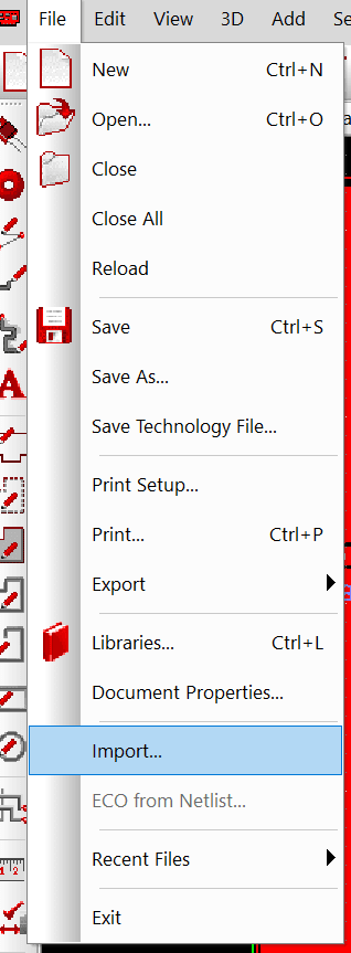
在 DesignSpark PCB 的 PCB 布局选项卡上,删除任何 PCB 电路板的轮廓,并从菜单栏中选择文件 -> 导入。选择所需的 DXF 文件。
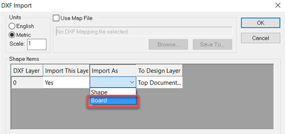
在打开的窗口中,为“导入为”选项选择“电路板”。
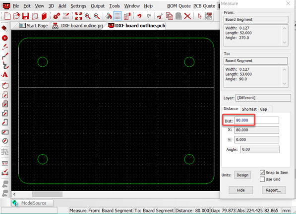
现在,电路板的轮廓将出现在 PCB 布局上,您可以根据需要选择并定位它。检查电路板轮廓的一个尺寸,以确保导入了正确的文件,使用测量工具可以很容易地检查尺寸。
使用 DesignSpark Mechanical 来创建电路板轮廓
*Please check if DesignSpark Mechanical can export the DXF format at your subscription tier
For complex board outlines it is often more convenient to design the board outline, cut outs and holes in a mechanical CAD package. DesignSpark Mechanical is ideal for this as you simply need to work in the 2D plane. Below is a simple example to illustrate the steps.
First create your board outline as required.
*请检查您订阅套餐中的 DesignSpark Mechanical 是否能导出 DXF 格式
对于复杂的电路板轮廓,在一个机械 CAD 软件包中设计电路板轮廓、切口和孔通常更为方便
DesignSpark Mechanical 是这方面的理想选择,因为您只需要在 2D 平面上工作。下面是一个简单的例子,它阐述了相关步骤。
首先按要求创建您的电路板轮廓。
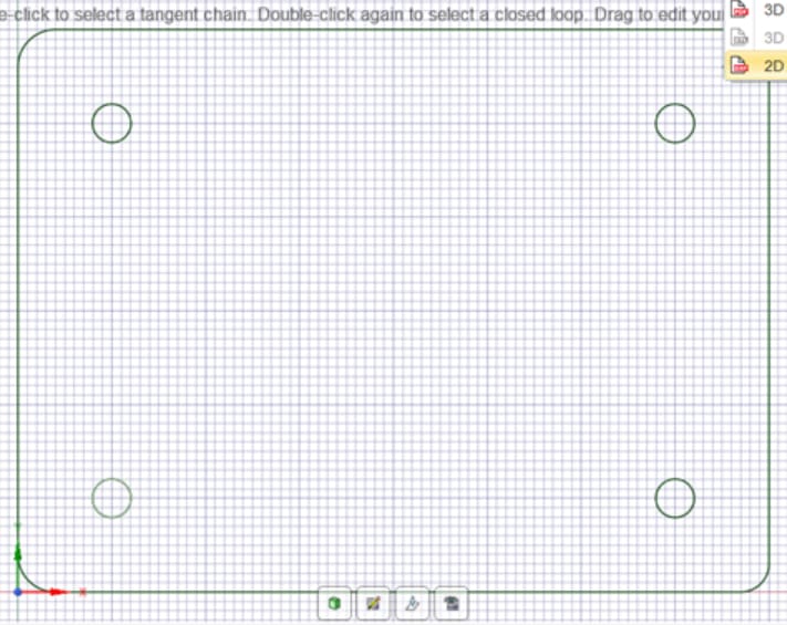
从导出选项中选择 2D AutoCAD(*.DXF),这将打开一个带有各种选项的文件保存窗口。
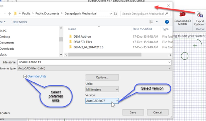
检查“单位”是否是您的 DesignSpark PCB 设计所需的,并选择 AutoCAD 格式版本,2007 版的基本 DXF 格式适合大多数用途。
您可以使用任何能生成 DXF 文件的机械 CAD 系统,但前提是它们必须符合 AutoCAD 所定义的 DXF 标准。如果您遇到任何问题,请尝试使用其他 AutoCAD DXF 版本。