A first look at the Digilent Digital Discovery
Suivez l'articleQue pensez-vous de cet article ? Aidez-nous à vous fournir un meilleur contenu.
Merci! Vos commentaires ont été reçus.
There was a problem submitting your feedback, please try again later.
Que pensez-vous de cet article ?
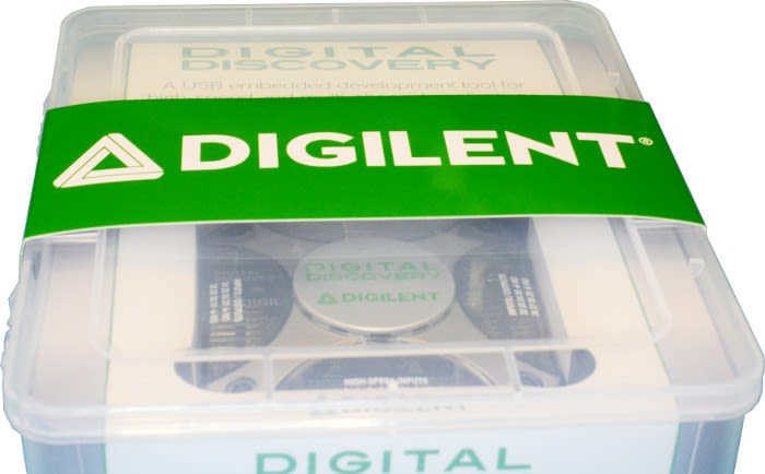
The Digilent Digital Discovery performs the function of both a logic analyser and signal generator in a robust neat little package. It shares a common form factor with the previously reviewed “Analog Discovery 2”. Rather than replace the analogue device it works well as a complimentary companion.
What’s in the box:
- The Digital Discovery main unit
- 2x connection leads
- A 1m USB cable
Specifications:
The full specifications are available here and to summarise:
- 24-channel digital logic analyser (1.2…3.3V CMOS, up to 800MS/s(with the High-Speed Adapter))
- 16-channel pattern generator (1.2…3.3V CMOS, 100MS/s)
- 16-channel virtual digital I/O including buttons, switches, and LEDs – perfect for logic training applications
- Two input/output digital trigger signals for linking multiple instruments (1.2…3.3V CMOS)
- A programmable power supply of 1.2…3.3V/100mA. The same voltage supplies the Logic Analyser input buffers and the Pattern Generator input/output buffers, for keeping the logic level compatibility with the circuit under test.
- Digital Bus Analysers (SPI, I²C, UART, I2S, CAN, Parallel)
As can be seen in the specifications this device has a lot of potential, providing a robust test harness for many purposes and circuits.
How is the device capable of such high sample rates via just a USB2 link? Unlike some other hobbyist logic analysers, this device has onboard memory and an FPGA for waveform sampling and generation. Because many of the functions are implemented in this FPGA fabric, the PC is offloaded, freeing up CPU and USB bus activity.
Waveforms 2015
Just like the Analog Discovery 2, the Digital Discovery uses Digilent’s own Waveforms software. We installed the software in the windows environment and were up and running in minutes.
Logic analysers excel at decoding
While an oscilloscope can be better at looking at individual bits, decoding a digital bus can be a time-consuming manual process and with more than a few channels almost impossible. This is where a logic analyser will hands down be the best tool in your arsenal. By the nature of the logic analysers operation, we get a logic LOW or HIGH vs. time, which makes it very simple to decode vast amounts of data.
A logic analyser is not an oscilloscope
At this point, we should discuss the differences between a logic analyser and an oscilloscope. Since both can analyse data it’s easy to confuse them.
A digital sampling oscilloscope is an analogue device in nature and will measure the voltage at a set sample rate, plotting this versus time. A logic analyser also samples at a given sample rate, however rather than measuring an analogue voltage it will sample a 0 or 1 depending on the voltage level and thresholds set within the analyser. The main point here is the different devices have different functions; while both can perform the same function it is not always optimal to do so.
Let's look at an example:
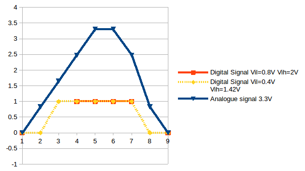
This is a simple analogue waveform and a sampling frequency around 9 points per positive pulse. We assume the analogue scope simply connects the points by straight lines (this is not typical oscilloscopes typically use sinx/x).
If we look at two different logic thresholds vs. digital output: the yellow trace is using an approximation of the Digital Discovery 3v3 thresholds; the red trace is using typical 3.3V logic thresholds. Both are sampling at the same rate as the analogue device.
The yellow trace will start to detect a logic high as soon as the voltage exceeds 1.42V and a logic low at below 0.4V; the red 2V and 0.8V respectively. The problem comes with a digital device when the signal is outside of these thresholds and it’s going to be unknown.
This is the reason the red trace only has points at time=1, 4-7 & 9. At time = 2,3 & 8 we don’t know the state. It’s highly likely to be the previous state but we cannot be certain this effect is the metastability region.
It is very important to bear this in mind when using a logic analyser, because if we have “unknown” samples then we may have incorrect data or timing jitter induced. This can also happen if waveforms start to “ring” — this is a high-speed effect (typically caused by parasitic inductance) and is much more likely to be an issue at 800Ms/s than 100Ms/s.
This looks like the oscilloscope is better — well in the sampling aspect it is — however, as a trade-off it requires oversampling by a large margin and the files/data produced is massive (float vs. bool). A logic analyser is 1bit per channel, therefore the data that is produced is much much smaller for large captures and the loss of voltage resolution is a massive benefit.
Flexible IO is a must
While most devices these days are 3v3 IO, there are still 5V logic applications out there. The Digital Discovery has this covered because of some clever input circuitry:
These circuits allow 1.8-3.3V input. 5V tolerance is added because of the “pot down” of the input (and a clamp).
The outputs are 3v3 push-pull or 5V open drain (requires a pull up to 5V).
Note that when operating at 5V OD the maximum speed of operation will be limed by the parasitic capacitance and the pull-up value. This type of system is typically limed to slower speeds and if you wish to push the discovery outputs it may be best to provide external level shifting when operating above 3v3.
Pattern generator
In our opinion, one of the most useful features of the Digital Discovery is the pattern generator. Allowing digital waveform generation from up to 8 I/O it can shortcut many tasks, allowing testing without committing to a microcontroller or FPGA design. We will be using this extensively for our next project. Not many devices offer such flexibility and we have been using microcontrollers for such purposes until now. Allowing us to simulate devices will shortcut much of the frustrating setup on those interoperability projects.
Programmable power supply
In addition to the above features, the Digital Discovery can provide a variable output power supply for driving external logic (low power only). This is a great “quality of life” feature and will again save much in the way of faffing when getting set-up and testing circuits.
A sneak peek
Here is a sneak peek at an upcoming item we are working on for an upcoming Chip Hack event based around the historic EDSAC computer. By using the logic analyser we can decode the output of a punched tape reader, allowing us to decipher the pin-out and drive electronics required to interface to an FPGA board for the event. Better still, because the Digilent Digital Discovery has a function generator capability, we can simulate our drive electronics directly from Waveforms 2015.
Final thoughts
While there are many cheaper logic analysers out there, they are unlikely to come close to the functionality of the Digital Discovery. It has quickly become a key part of our toolkit sitting alongside the trusty oscilloscope to give us the best of both worlds. Allowing both capture and output from a single device is a great addition to our debug capabilities and will be of much use in the future.
Karl Woodward


Commentaires