Microcontroller Interfaces: PMDC Motors
Follow article
 Dave from DesignSpark
How do you feel about this article? Help us to provide better content for you.
Dave from DesignSpark
Thank you! Your feedback has been received.
Dave from DesignSpark
There was a problem submitting your feedback, please try again later.
Dave from DesignSpark
What do you think of this article?

A motor-gearbox unit provides the drive for one side of this two-wheeled ‘buggy’ mobile robot. The output shaft emerges on both sides of the gearbox, carrying the road wheel on one side and a slotted-disc tachometer wheel on the other. The latter works with the IR beam-break detector module underneath it to provide rotational speed feedback to the MCU. The board bolted to the side of the motor contains two H-bridge controllers, one for each drive. All the parts and boards shown are widely available from many Internet-based suppliers.
How does a PMDC motor work?
The humble brushed permanent magnet DC motor is still the favourite for designers of small mobile robots, traction systems and toys. It consists of three main components:
- The outer casing with two permanent magnets installed inside forming the Stator.
- The Rotor or Armature, consisting of at least two copper wire coils (windings) wound on an iron core that rotates within the stator.
- The Commutator and Brushes which allow a power supply to be connected to the rotating coils. The commutator is split into isolated segments so that the current flowing in each coil reverses direction as the shaft rotates.
Each coil forms an electromagnet with North and South poles which tries to align itself with the poles of the stator’s permanent magnetic field. The physical arrangement of the motor ensures that the resulting magnetic force appears as a mechanical torque on the shaft. In other words, it’s is the interaction between the stator magnetic field and the rotor electromagnetic field that causes the rotor to rotate. The shaft continues to rotate because the commutator reverses the polarity of the coil’s field just as the magnetic and electromagnetic poles line up, forcing the rotor to move on. For a working motor you need a minimum of two coils with the commutator split into two 180° segments. A practical motor requires at least three coils and three 120° segments. A two-coil motor will not self-start and may ‘lock up’ when the north and south poles of the stator and rotor fields line up. In this condition, the brushes will probably be straddling the segment gaps, shorting out the coils and the power supply. Adding a third coil eliminates this problem and ensures self-starting. High-quality motors have at least five coils, sometimes more to ensure much smoother operation. The beauty of the PMDC is its simplicity and the linearity of its operation (Fig.1).
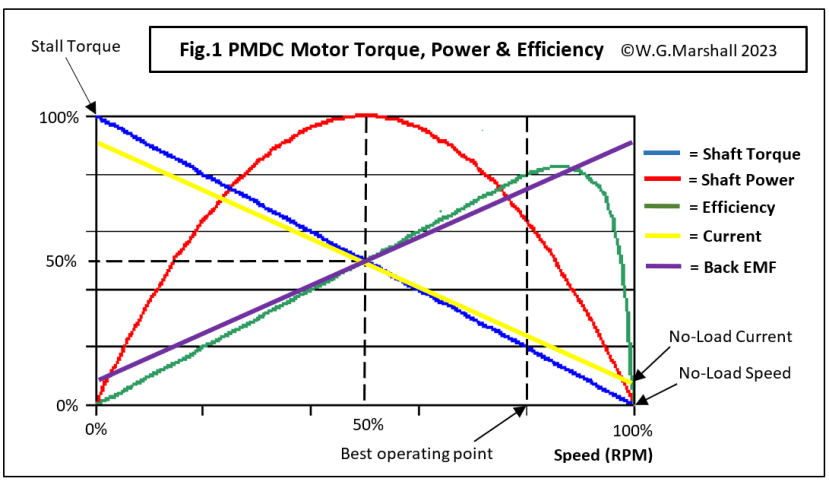
Ignoring the ‘Efficiency’ line, notice the symmetry of the curves centred around 50% of rated speed on the horizontal axis. Although this is an ‘ideal’ representation, it’s close enough to reality for practical design calculations to be made. Key things to notice:
- Maximum Torque occurs at zero rpm (aka Stall Torque); the situation that exists when power is first applied to the motor terminals. That characteristic accounts for the incredible acceleration figures quoted for electric vehicles. For example, at the time of writing a Tesla Model S car has a 0 to 60mph time of 2.0 seconds.
- The coil Current curve follows the Torque curve almost exactly: unsurprisingly maximum current flows at maximum torque, falling to near zero at full speed with no load.
- At zero speed, a heavy current flows in the windings because they have only a tiny resistance. Once the rotor starts turning in the stator’s magnetic field, it becomes a generator producing a voltage opposing that of the power supply. It’s called Back-EMF which rises as the rotor speeds up to a point just below the supply voltage at maximum rpm. That’s what causes the rotor winding current to fall.
- When a load-torque is applied to the shaft, the speed drops causing the motor current and torque to rise again. If the load becomes too great, the rotor eventually stops turning and the motor is said to have ‘Stalled’. Allowing this situation to prevail will inevitably lead to a ‘burn-out’ of the motor or drive electronics. Or both.
Driving a PMDC Motor
The simplest circuit consists of a switch and a dc power supply, if you just want on/off with no directional control. A practical project is likely to need an electronic switch - a MOSFET or Bipolar Junction Transistor (BJT) device, controlled via a microcontroller GPIO pin (Fig.2a). The simple single-transistor circuit shown is suitable for low-voltage ‘hobby’ motors with a stall current less than 1A. Note the diode D1 to protect the transistor from the high reverse voltage that occurs when an inductive load is switched off. The capacitor C1 also helps to reduce EMI generated by the motor’s commutator action.

Direction Control
If control over the direction of rotation is required, this can be achieved with an H-Bridge circuit (Fig.2b). It’s a very popular circuit and widely available packaged in a single chip. Once again, the switch element can be a single BJT or MOSFET, with diodes and a capacitor performing the same protection function as before. This particular configuration uses an NPN/PNP BJT pair on each side of the bridge with a common Base connection to an MCU GPIO pin. There are only four states possible from the two GPIO logic inputs A and B, and these are presented in the truth table. To get current flowing through the motor, the upper (PNP) transistor on one side must be turned on, along with the lower (NPN) transistor on the other side.
So, for current to flow from left to right, TR1 and TR4 must both be switched on while TR2 and TR3 are off. This is achieved by taking input ‘A’ low (0) and input ‘B’ high (1). Because TR1 and TR2 share the same Base input, the low on A that turns PNP transistor TR1 on, also turns NPN TR2 off. Input B drives TR3 and TR4 in the same manner.
Hitting the Brakes
A PMDC motor has a unique characteristic: if the power is turned off and its terminals are shorted together, the rotor current and field briefly reverse, opposing the turning force and braking the motor to a quicker stop than if the terminals had not been shorted. Why does this happen? Remember that when the motor is running, it acts as a generator, producing a voltage or Back-EMF which opposes the supply voltage. If the supply voltage is suddenly cut off and the terminals shorted, mechanical momentum keeps the rotor turning and the continuing Back-EMF has nothing to oppose it. The result is a short-circuit current flowing in the opposite direction, which reverses the previous field polarity bringing the rotor to a rapid halt. This reverse current is very large and short-lived, but could cause severe overheating of the coil windings and switching transistors - even burn-out. Mainly a problem with large (industrial) motors, the solution is to replace the short-circuit with an external resistor bank to dissipate the heat. Fortunately, I’ve not found it necessary to use such complications with small ‘hobby’ motors.
We can recreate the braking effect by using the circuit of Fig.2b and setting A = B = 0 or A = B = 1. In the latter case, both TR2 and TR4 are turned on while TR1 and TR3 are off. If A had previously been low and motor current was flowing left to right via TR1 and TR4, the now-reversed current flows through TR2, along the 0v connection, and then back via the Catch diode D4 to the motor. The motor doesn’t stop instantly, but it certainly slows down faster than when the motor supply is simply turned off. If you need the drive to stop abruptly, make sure that you use a motor gearbox containing a worm-gear and pinion. A worm-gear drive is unidirectional – the worm can turn the pinion, but not the other way around. Turn off the motor supply alone and the output will continue to rotate for a couple of seconds thanks to momentum. Include the short-circuit and the result is a dead stop because the motor direction is reversed but the gearbox rotation is not, causing the worm and pinion to lock up.
Shoot-through
Another feature of the H-bridge circuit of Fig.2b is that it makes it impossible for both transistors on one side of the motor to be turned on at the same time, a situation which would short-circuit the power rails with fatal consequences for the two devices! However, if one transistor switches on slightly quicker than the other turns off, then we have a condition called shoot-through – a short-circuit that lasts for just a fraction of a nanosecond. I’ve not found it to be much of a problem with these low-current circuits, particularly as I use transistors with matching characteristics such as the BC639 (NPN) and BC640 (PNP).
Alternatively, driving the transistors independently by giving each its own GPIO output can provide a software solution. The MCU can be programmed to ensure that transistors are turned off slightly before its partner on the same side of the bridge is turned on. The big danger with this technique that a coding error could lead to both being switched on at the same time!
Speed Control
Most applications also need a means of varying the motor speed, especially if some sort of feedback control system is to be used (see later). It can be deduced from Fig.1 that PMDC rotation speed is linearly related to the supply voltage. Directly varying the voltage by operating the driver transistors in their linear region using a digital to analogue converter (DAC) would work, but at a cost of massive power wastage in the form of heat. A much more elegant method is to drive the switches with a digital Pulse Width Modulation (PWM) signal (Fig.3).

This is by far the best method of speed control because:
- The mark-space ratio of the pulse train is directly proportional to the average voltage.
- The drivers are still switched between on and off, minimising power dissipation.
- Most modern MCUs have on-chip PWM signal generator hardware.
The PWM signal is added to the H-bridge circuit by AND-gating it with the other input signals so that all the switches are turned off while it is low and enabled when it’s high. This means that power is applied to the motor during the high phase and turned off during the low. The motor freewheels or ‘coasts’ during this off period. If all the switches are turned off via the control signals, the motor will slow down and stop – how long it takes will depend upon the load.
PWM Frequency
A question often asked is: ‘What PWM frequency should I use?’. In principle, anything up 20kHz can be used to get it out of human hearing range. I have found that with small hobby motors, it’s hard to get a reasonable range of speed control with much more than 250Hz. One explanation may be that the very narrow pulses of a high-frequency signal are just not long enough to ‘kick’ the rotor into action. One thing is certain: it depends on the motor, and a certain amount of experimenting may be needed.
A Single Chip: The L293D Quad Half-Bridge
As I suggested earlier, the H-bridge circuit is so useful it’s available in various forms from a number of chip manufacturers. The L293D (714-0622) for example, has been around for a long time and is very popular with designers needing an interface between a microcontroller and small DC motors with up to 1A of stall current. The chip actually contains four ‘half-bridges’: the latter being the pair of transistor switches on each side of the ‘H’. In other words, one chip can be wired up as two independent H- or Full-Bridges to control two motors (Fig.4).

Note that extra internal logic combines the two control signals for each half-bridge into a single Mode input and adds an enable input for the PWM signal. On-chip Catch diodes are provided, so the only other component worth including is a capacitor soldered across the motor terminals.
For heavier current applications there is the L298N (370-6953) device which can handle stall currents of up to 4A. This chip requires external Catch diodes to be attached, but it does offer a facility for monitoring the motor current: a low-value resistor can be fitted in series with each motor’s 0v connection. H-bridge circuits are so useful that most manufacturers of expansion boards for MCU development kits will have one or more in their ranges. For example:
Digilent Pmod HB3 2A H-bridge module (134-6445)
MikroElektronika DC Motor Click 1.5A H-bridge module (820-9801)
Seeed Motor Bridge Cape for BeagleBone (174-3284)
Infineon Motor Control HAT for Raspberry Pi (228-6713)
Air-cored PMDC motors
The latest PMDC motor designs feature ironless, tubular coil armatures rotating around the permanent magnet stator. Expensive, but they can accelerate/decelerate very quickly and offer much greater efficiency than the standard iron-cored type. It was an ironless motor, slightly modified for use in Space, that provided the motive power for the Mars Exploration Rovers Spirit and Opportunity for many years – way beyond their original mission lifetime.
Finally: Closing the Loop
Summary of what we have so far: An interface that provides precise control over motor speed and direction from a suitably programmed microcontroller via the latter’s digital GPIO ports. We also know that the motor speed is pretty much directly proportional to the voltage across its terminals. Now, motor datasheets usually specify the maximum no-load speed (in RPM) at a maximum rated supply voltage. They will also provide a figure for the Stall torque (in Nm, or for small stuff, N-cm). Using these numbers, you should be able to select the right motor for your application, say, a wheeled robot. It will have to travel fairly slowly at a speed set by the MCU program and be able to maintain that speed on sloping or rough terrain. Under these circumstances a reduction gearbox is essential. Unfortunately, the motor characteristics are not compatible with this aim, because the speed falls as the load torque increases. To cut a long story short, some sort of sensory feedback is necessary to vary the terminal voltage automatically, in response to uncommanded speed changes caused by the terrain. My article on robot mobility control provides a lot more detail on the subject of PID control, and shows how the focus for project development moves swiftly from hardware to software.
Next Time
More on the subject of motor interfacing.
Articles in the series
This short series of articles is the basics of interfacing peripheral components to a microcontroller (MCU).
- Microcontroller Interfaces: LEDs and Lamps - In this first instalment, the simplest of display devices are considered: the single LED and the filament lamp.
- Microcontroller Interfaces: Switches and Buttons - In this second instalment, the simplest of input devices are considered: the mechanical switch and the pushbutton.
- Microcontroller Interfaces: Electromagnets and Solenoids - In this third instalment, I’ll show how special care is needed when designing an interface for an electromagnetic actuator.
- Microcontroller Interfaces: PMDC Motors (this article) - In this fourth instalment, we look at Permanent Magnet DC Motors, they are cheap, have linear characteristics and are very easy to control using the PWM units built-in to most modern microcontrollers. Interfaces can be as simple as a single transistor depending on the application.
If you're stuck for something to do, follow my posts on Twitter. I link to interesting articles on new electronics and related technologies, retweeting posts I spot about robots, space exploration and other issues.