Microcontroller Interfaces: Switches and Buttons
Follow article
 Dave from DesignSpark
How do you feel about this article? Help us to provide better content for you.
Dave from DesignSpark
Thank you! Your feedback has been received.
Dave from DesignSpark
There was a problem submitting your feedback, please try again later.
Dave from DesignSpark
What do you think of this article?
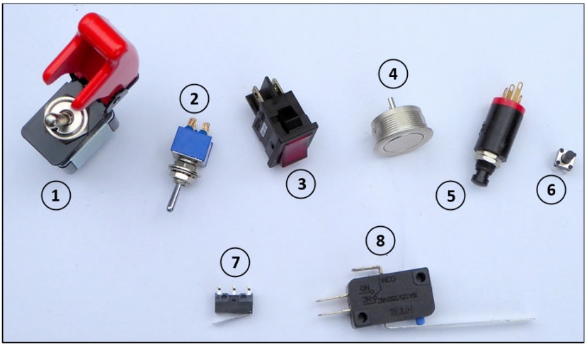
A by no means exhaustive collection of toggle and pushbutton switches.
Introduction
This is the second part of a short series of articles on the basics of interfacing peripheral components to a microcontroller (MCU) based system. Last time I covered simple output devices for monitoring the status of a single GPIO output pin; now it’s the turn of equally simple input devices: mechanical switches and pushbuttons. Before discussing interfaces, let’s look at some actual switch hardware and discuss why relatively complex hardware and/or software are needed to read the switch state reliably.
Some switch terminology
Toggle switch. Usually refers to devices with a toggle or lever actuator as in [1] and [2] of the heading picture. Confusingly, it also refers to the toggle action of a switch moving between two distinct states. But when you see the term toggle-switch in catalogues, it’s used to differentiate it from the modern rocker switch as in [3].
- Single-Pole Single-Throw (SPST). A basic on/off switch with two connections.
- Single-Pole Double-Throw (SPDT). A 2-way switch with three connections, as shown in Fig.3.
- Single-Pole Changeover (SPCO). An alternative term for SPDT.
- Double-Pole Single-Throw (DPST). Two basic on/off switches with four connections.
- Double-Pole Double-Throw (DPDT). Two 2-way switches with six connections.
- Double-Pole Changeover (DPCO). An alternative term for DPDT.
- Momentary NO. Pushbutton switch spring-loaded to return to OFF state when released.
- Momentary NC. Pushbutton switch spring-loaded to return to ON state when released.
- Latching. Pushbutton that holds new state until pressed and released again.
Some typical switches
The heading picture above illustrates a selection of devices found after rummaging through my spares boxes recently.
[1] A good old-fashioned toggle switch. You rarely find these on modern equipment nowadays, certainly not driving logic inputs, but they still have their uses for manual control of high-current ac mains supply. This one can handle 250Vac at 3A, and benefits from a moveable shield which prevents accidental operation. In the picture, the red spring-loaded cover is shown in the raised position, permitting switch operation. When in the down position, the internal structure of the cover prevents the toggle from being pushed forward. An extra safety feature allows for an ‘emergency off’ by flipping the heavily-sprung cover back, forcing the switch back to its original position. You frequently see these safety covers used on ‘arming’ switches that control the motor power supplies of potentially dangerous mobile robots.
[2] A miniature version of the above, but with the same voltage/current rating. An advantage of this format of toggle switch is that they only require a circular hole to be drilled in a panel to mount them.
[3] A neat plastic ‘rocker’ type switch rated for 250Vac at 4A. This one contains a neon bulb and can be wired to glow red when the mains is switched on. Rectangular rocker switches are more difficult to fit, as a rectangular hole needs to be cut. But, once the hole is cut, they generally just ‘click’ into place.
[4] The first of three momentary-action pushbutton switches. It’s an example of a ‘ruggedised’ button designed to operate outdoors and resist vandalism.
[5] A cheap pushbutton for experimental rigs only: definitely for careful indoor use only.
[6] A tiny PCB-mounting ‘Tact’ pushbutton. You will find these on most MCU development boards for functions such as Reset, but also ready-wired to user GPIO pins.
[7] A miniature ‘microswitch’: a low-voltage/current version of [8]. Pressing the free end of the little hinged lever causes the switch to operate. These are frequently used as ‘bump sensors’ on small mobile robots.
[8] A classic ‘microswitch’ with a long operating lever. Very common devices, but rarely seen as they are used inside electromechanical equipment to sense the position of moving parts. A typical use is as a limit switch, shutting off the power when a lever has moved as far as it can go, thus preventing damage, or a burned-out stalled motor. They are traditionally ac mains rated because they controlled motors, relays and solenoids directly – long before the advent of computer control.
Basic digital interface (Fig.1)
Hardware interfaces don’t come much simpler than a single resistor. Actually, they do. Many MCUs feature programmable ‘weak-pull-ups’ on some or all of their GPIO pins, eliminating the need for an external resistor. But why is a pull-up needed at all?
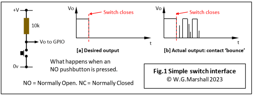
GPIO inputs have a high input impedance. That means they only require tiny amounts of current from the external circuits driving them. The low current requirement is obviously advantageous when an output is connected to it, but becomes a liability if an input pin is left ‘floating’ with nothing connected. The 10kΩ resistor in Fig.1 is connected between the GPIO input and the supply voltage for the chip +V. With no pull-up and the switch open, the input pin acts like an antenna picking up stray electromagnetic noise and feeding it into the chip. Even if the pin is not ‘read’ by the program, that noise can cause internal circuits to malfunction. Hence the need for a pull-up, which stops the pin ‘floating about’ between the logic 0 and logic 1 threshold voltages. The resistor value must be a lot smaller than the input impedance to ensure a low volt drop across it, but large enough to avoid a current surge when the button is pressed. Unused input pins should always be pulled up to avoid the noise problem. It’s usually OK to connect unused input pins directly to the power rail during development, that is, with no resistor. The practice is frowned upon for production units, however, because an internal chip failure might result in a short-circuit to ground, causing a lot of extra damage.
Weak Pull-Ups
The pull-up in Fig.1 is weak because the high value of the resistor will only allow a fraction of a milliamp to flow when the button is pressed. Logic chips tend to have FET inputs nowadays with very high input impedances (MΩ), so when not being pulled down by a driver, next to no current flows through the resistor and it behaves like a wire connection to +V. If that were the only selection criterion for pull-up resistor value then just about any value would do, so long as it’s a lot less than the logic input impedance. And, the device driving that input has a negligible source impedance, such as a mechanical switch or pushbutton. Incidentally, a low-value resistor is known as a strong pull-up.
An additional design consideration comes in when the driver has a high source impedance and/or there is a lot of electrical noise about. A high source impedance will not allow enough current to flow when the button is pressed and the input will not see true ground. Of, course this won’t apply here (unless you’re using some pretty grotty switches). Problems may occur if an electronic circuit is driving the input, one with what’s called an Open Collector, (or for FET, Open Drain) output. More about that when we look at relay and solenoid drivers.
Bouncing switches
The ideal response from our switch/pull-up resistor is shown in Fig.1a – a nice clean edge to ground when the switch is closed (or button pressed), But see what actually happens in Fig.1b – the signal ‘bounces’ randomly all over the place, often for up to 10ms. The sprung-loaded nature of the moving contact (pole) causes it to bounce around on and off the fixed contact before settling down to a steady state. You don’t notice this effect with a mains light switch because it takes many milliseconds for a filament lamp to come up to full brightness. LED lamps don’t seem to be affected either. On the other hand, a logic or computer input is very definitely going to be noticed, particularly interrupt inputs and clock signals.
Debouncing circuits, analogue filter type (Fig.2)
A simple but effective solution to switch bounce is to add an analogue low-pass filter with an RC time constant in the region of 10ms. This converts the signal state and the bounce pulses to a nice, smooth curved falling waveform. That’s no good either, because logic likes fast edges, not smooth curves. What we need is a smooth-curve to fast-edge converter, also known as a Schmitt trigger. All logic families have one of these, usually available in a package of six. I’m using a 74HC14 device here, a hex Schmitt inverter. The hysteresis of the Schmitt inverter means that its output only switches high when its input falls below a threshold voltage – about 10ms after the button was pressed. For most applications, this delay is of no consequence, but at least we have a single rising edge. When that delay is a problem, there is another solution involving a set-reset flipflop and a changeover switch.

Debouncing circuits, set-reset flipflop type (Fig.3)
This to me is the best solution: the SPCO button or switch is probably a bit more expensive, but it delivers clean edges with no delay. Check the truth table to see how it works. The key thing to note is that the first meeting of the pole with the open contact toggles the flipflop to its alternate state and subsequent edges do not change that, no matter how long the bounce interval is. The switch has to be flipped back to its original position to toggle the output once again. Note that the GPIO input no longer needs a pull-up, because the NAND gate has a 'totem-pole' output able to drive it both up and down.

Other methods
If your MCU has programmable weak pull-ups available then an entirely software-based solution is possible: loop while waiting for the GPIO pin to go low (or use an interrupt, many PIC chips have Change Notification Interrupts for just this situation), then enter a delay loop for 10ms before reading the port again. By this time everything should have stopped bouncing around and the data become stable. Purists tend not to like the software approach, mainly because of the aforementioned delay in responding to what could be a very important signal. But it’s up to the designer to determine which switch inputs are so critical as to need an instant response. In 99.9% of cases, the software solution will work just fine. Here is an example, albeit based on ancient technology, of a mechanical system that encoded/decoded a serial data stream in just this way, with delays provided by a rotating camshaft.
Next Time
I’ll be looking at simple electromechanical devices – relays and solenoids.
Articles in the series
This short series of articles is the basics of interfacing peripheral components to a microcontroller (MCU).
- Microcontroller Interfaces: LEDs and Lamps - In this first instalment, the simplest of display devices are considered: the single LED and the filament lamp.
- Microcontroller Interfaces: Switches and Buttons (this article) - In this second instalment, the simplest of input devices are considered: the mechanical switch and the pushbutton.
- Microcontroller Interfaces: Electromagnets and Solenoids - In this third instalment, I’ll show how special care is needed when designing an interface for an electromagnetic actuator.
- Microcontroller Interfaces: PMDC Motors - In this fourth instalment, we look at Permanent Magnet DC Motors, they are cheap, have linear characteristics and are very easy to control using the PWM units built-in to most modern microcontrollers. Interfaces can be as simple as a single transistor depending on the application.
If you're stuck for something to do, follow my posts on Twitter. I link to interesting articles on new electronics and related technologies, retweeting posts I spot about robots, space exploration and other issues. To see my back catalogue of recent DesignSpark blog posts type “billsblog” into the Search box above.