3D Printing from Recycled Plastic Bottles, Part 3
Follow article Dave from DesignSpark
How do you feel about this article? Help us to provide better content for you.
Dave from DesignSpark
Thank you! Your feedback has been received.
Dave from DesignSpark
There was a problem submitting your feedback, please try again later.
Dave from DesignSpark
What do you think of this article?
In this final part of the DIY pulstrusion odyssey, I build the mechanical winding end of the system and set about tinkering with pulstruding and printing with the DIY filament. As a recap in part one, we looked at different tools and methods for stripping the bottles into long continuous 6/7mm wide strips of plastic. In part two we concentrated on the hot end system, making a custom nozzle that sits inside an off-the-shelf PID-controlled jacket heater. We got as far as manually extruding a short length of filament by pulling the plastic through the system by hand with a pair of pliers.
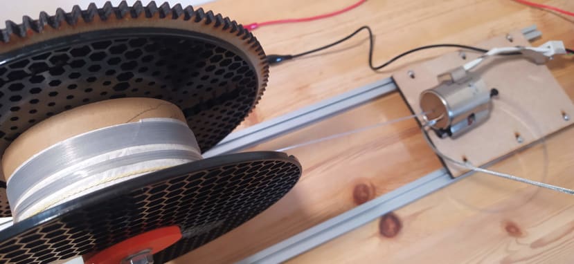
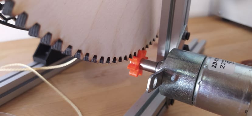
For the winding system, we need some kind of rotating drum that has a reasonable amount of torque to pull the extruding filament through the system and wind the filament onto it. An obvious idea I ran with, was to reuse an empty filament reel as the basis of the winding drum. As it needs reasonable torque a lot of people building pulstrusion systems have opted for a stepper motor to drive a geared wheel. In many ways, this makes sense, especially if you are using a donor 3D printer as the hot end system as you will likely have a stepper motor and driver system on the 3D printer control board. We had seen though that some people had opted to use DC motors of varying types geared down, or controlled to create a low speed hi torque system. Experiments with the manual extrusion of filament from the hot end informed the design in helping estimate a reasonable extrusion speed of perhaps 150-250mm per minute. With that in mind, we found a geared DC motor in our collection that ran at 18rpm at 12V. With some investigation, this motor is sold online under the brand BQLZR and has a part number of NO2998. Obviously, 18rpm is still a little much in terms of directly coupling the motor to the filament reel so a simple gear system was made to reduce the speed even more so. I used a couple of techniques to make the gears, the small pinion gear attached onto the motor shaft I drew using CAD and the gear generator tools and workbench. 3D printing a small gear such as this is a short job for a 3D printer. For the large gear we made to attach directly to the filament reel, I drew a gear using the same tooth geometry as the pinion gear but in Inkscape so that I had a large 2D design. This meant I could laser-cut the gear from some 6mm plywood, you could absolutely 3D print this part, and indeed probably print it in sections, but if you have access to a laser cutter it’s a few minutes of a job compared to a few hours. Alternatively, it would be pretty straightforward to make a pulley-based system perhaps using GT2-style belting.
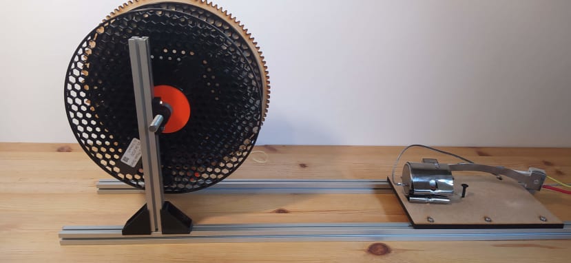
The frame for the winding system was assembled using some 15*15mm aluminium extrusions which were connected together with some M3 nuts and bolts and some 3D-printed brackets. The larger plywood gear was glued to the empty filament reel and a couple of large plastic washers were 3D printed to reduce the centre hole of the filament reel (around 53mm diameter) to 8mm which in turn sat on a simple axle made from a short length of 8mm threaded rod. Again some super simple bearing blocks were designed and printed and attached to the vertical legs of the assembled extrusions and the 8mm axle holding the winding drum and gear are simply placed through the 3D print. A good upgrade down the line would be to redesign this section to use some simple skateboard-style bearings to make this more efficient and less prone to wear.
The simplest way to attach the motor to get this system up and running was to use two of the motor mount legs to replace a plastic bracket bridging a horizontal base section and the vertical. This has worked well but is on the list of things to potentially improve. If we redesigned the motor mount to sit elsewhere we could reduce the height at which the drum sits relative to the pulstrusion extruder nozzle. At the moment the extruded filament is pulled upwards from the nozzle at around 20 degrees towards the drum. It feels like it would be more efficient if we could reduce that pulling angle.

A small base was made for the other end of the system for the hot end to sit onto. After some testing of the motor drive system, we then turned our attention to the issue of how to attach the extruding filament to the winding drum. The simple solution is to attach a piece of kevlar cord around the drum centre. We tied this around the centre of the drum and added some extra overhand knots to the excess end. We then just used some tape to stick over the knots which created enough grip for the loop not to spin on the drum centre. Leaving some of the kevlar string long enough to reach out past the extruder hot end nozzle we tied a small loop in that end. We then took an M3 nylon standoff nut and slightly drilled one end so that a small 4mm hole was formed to a depth of around 4mm. We can then thread the kevlar loop through the standoff from the undrilled side with the drilled side facing the extruder hot end. When you load the bottle strip into the pulstruder you cut the end of the strip into a long thin point and push that point through the nozzle. Once the pulstruder comes up to the operating temperature you then manually extrude a little filament and then push the strip through the loop and fold the strip back on itself. You then pull the loop and the folded strip back into the nylon standoff where it should, perhaps with a couple of practice runs, lock into position.

It’s true to say that if you build a pulstruder you’ll need to experiment a lot with temperatures and speeds to find out what works for your system. For this system, it seems a temperature setting for the hot end that works well is 235C. However, I’m aware that the thermistor is mounted around 10mm away from the dead centre of the nozzle so this might not be the actual temperature at the point of extrusion. Whatever you build though should be consistent, so I’m reasonably assured that the 235C setting on the PID controller gives me the same temperature at the nozzle every time. Temperature is reasonably critical, if the temperature is a little low it’s hard to pull the strip through the extruder but a few degrees too hot and the plastic melts to a point where the torque of the pulling system will just break it.
I’m running the motor currently using my variable DC benchtop power supply. It’s noteworthy that there is way more torque in the system than is actually needed and so I can undervolt the motor, even down to 3V and it still has plenty of torque to pull the filament through the system, this means I can experiment with motor speed without using any additional motor control gear. With that all said, the system works very well. There are a few refinements I plan to make. The most notable is that I would like to create some kind of cassette system for the bottle strip end of the system as currently, you need to keep a watchful eye that the bottle strip is sliding into the back of the nozzle correctly. A more regulated input system for the bottle strip, perhaps with some kind of “end of strip detection” would enable the pulstruder to work in a more standalone mode. A final modification I'm considering is adding some kind of clutch or way to disengage the drum from the motor and gear system so that you can unspool your DIY filament with ease.

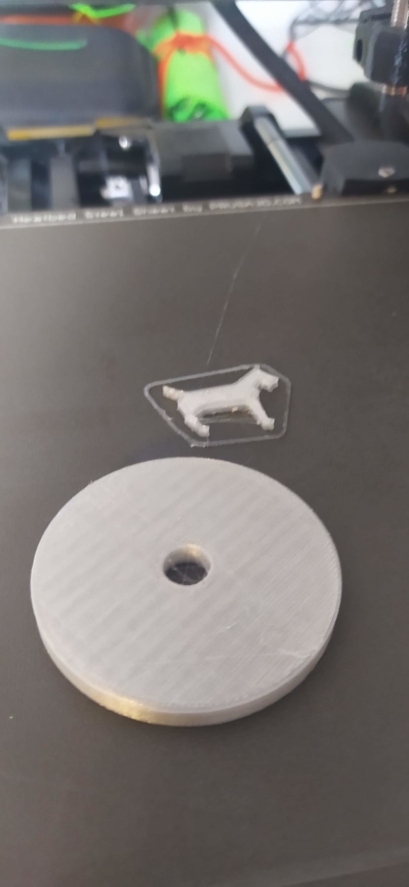
With some filament extruded, we need to look at how to print with this filament. This can seem quite daunting in the first instance but actually, it’s pretty straightforward. It prints similarly to PETG but as this is PET it requires slightly higher temperatures. I’m finding 265C at the printer nozzle and 80-90C bed temperature is working well.

The other significant difference with our DIY filament is that it is consistently slightly under size. This is very common with DIY pulstrusion and often is much worse than our system. We’ve seen some systems where there is quite a sharp short angle lead into the pulstruder nozzle and this can mean that the resulting filament isn’t totally round but actually, you can see a U shape where the strip has been essentially folded into a near round geometry. With our more relaxed nozzle, we are getting cylindrical filament but often with a tiny void running down the centre. You can easily mitigate these problems though by adjusting the flow rate or the extrusion multiplier in your slicer software. With the DIY filament our system creates, we have found we are getting well-extruded accurate parts when we up the extrusion multiplier up to 1.25 from 1.

As a final thought, we realise that pulstrusion isn’t for everyone, but it is an affordable cost-effective way of making filament in a sustainable way that reuses these single-use plastic bottles. It’s quite a pleasant surprise just how well the DIY PET filament prints, it seems equivalent with quite expensive branded PETG in terms of print quality. With many printers now having filament detection it’s not too bad in terms of having to load a next section of DIY filament every half hour or so and there are many in the pulstrusion scene working on easy techniques to splice bottle-length portions of PET into longer continuous spools. It’s certainly great to make parts and be able to slightly brag that they were a bottle the day before!