Remote TCP-IP Display for Raspberry Pi
Follow project
 Dave from DesignSpark
How do you feel about this article? Help us to provide better content for you.
Dave from DesignSpark
Thank you! Your feedback has been received.
Dave from DesignSpark
There was a problem submitting your feedback, please try again later.
Dave from DesignSpark
What do you think of this article?
 How to monitor temperature on the Raspberry Pi and visualize the results on a remote TCP-IP display and OKdo Cloud.
Parts list
| Qty | Product | Part number | |
|---|---|---|---|
| 1 | Raspberry Pi | 137-3331 | |
| 1 | Riverdi IoT Display | RVT50UQENWC0x | |
| 1 | Zerynth Studio | Zerynth Studio | |
Introduction
When you’re discussing the topic of creating a new product, an unavoidable topic is the “Time to Market“ period. Today’s consumer electronics market demands it to be the shortest possible and due to that fact, many hardware and software manufacturers are choosing “ready-made tools” which can speed up the whole process. There is no modern startup business plan in which minimum viable product (MVP) is not one of the most important topics and represents the first step to the final and successful product – so it is important to say that “ready-made“ tools and solutions can significantly decrease time to achieve that so important milestone.

This article will introduce you to the Riverdi IoT Display, as a representative example of the “ready-made solution”, through step by step instructions on how to make a demo application named Remote TCP-IP display for Raspberry Pi.
While we are proving the title of “representative example” through the instructions you will be also introduced to some features of the module which might give you a resolution to some questions related to design and development of this type of products or even more – an idea how they can be used inside your existing product.
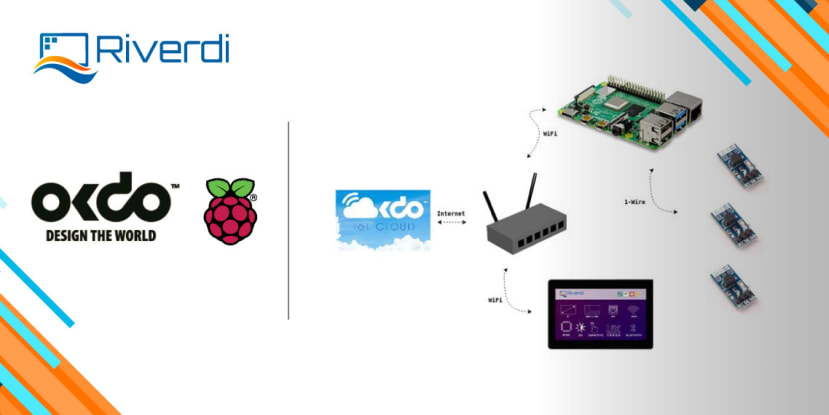
Remote TCP-IP Display system architecture
The aim of this demo project is to design and implement a system where the Riverdi IoT Display will be used as a central unit of the system which collects data from the cloud and displays it on the screen. Communication with the Cloud platform will be established using Wi-Fi connection and TPC-IP protocol. The Raspberry Pi, as another system unit, will supply the Cloud with the data – in this case, we will send information about current system status including the CPU temperature and CPU usage. As the Cloud platform, we will use the OKdo Cloud, but it is important to say that any other can be used as well.
We will also provide instructions on how you can visualize the data on the OKdo cloud.
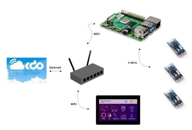
The whole system should be easily integrated into the usual living environment, so we are assuming that you already have a Wi-Fi router with Internet access.
The implementation will start with the OKdo Cloud and the creation of the account and preparation to receive data by creating the keys. Then we will go to the Raspberry Pi where we will try to supply the Cloud with local measurements using the node.js framework. Finally, we will go to the Riverdi IoT Display where we will establish a connection with the Wi-Fi router, and then establish the communication with the Cloud platform. In the end, we will visualize data that we got from the Cloud.
Getting started with Riverdi IoT Display
The main and most important component of the demo application, from our POW and the POW of an embedded developer, is the Riverdi IoT Display. So, let’s just go through the most important features of the display.
The Riverdi IoT Display carries an 800×480 resolution display, 5″ diagonal, capable of presenting 16.7M colors, which is more than enough for the purpose of an IoT Display. The display is driven by Bridgetek’s BT815 graphic controller. The customer has a choice to select between a capacitive and a resistive touchscreen sensor. The board also carries additional 2 mikroBUS expansion sockets allowing you to easily extend the functionality of the board. The heart of the board is the well known Espressif’s ESP32 SOC, popular among the embedded population of any kind – hobbyists, professionals, beginners. The board can be power supplied through a USB connector, which is also used for programming of the ESP32. There is also a standard 5V battery connector.
It is important is to say, that the display is ready to be mounted on a wall straight from the box. Be it with mounting holes or already placed sticky areas, it proves the “ready-made” solution concept from the beginning and allows you to mainly focus on software development.

On another note related to software development – the developer has a wide spread of choices. When talking about programming languages – you can choose between: C, Python, Lua, JavaScript or even Ruby. The number of frameworks usable on this board is permanently increasing, the most famous ones are Espruino (Node.js) and NodeMCU (Lua), but our favorite is, for sure, Zerynth (Python). Thanks to Riverdi’s partnership with Zerynth, the display has a pre-loaded Zerynth Studio license, so that you can start working with the module right after getting it outside of the package.
OKdo cloud platform
The first step in this section as part of prerequisites is to create an account on the OKdo cloud – so go to OKdo and sing up.
After you login go to the “Playground” what we must do is create two devices. The first device will be used to supply data from the Raspberry Pi and the second device will be used to read data using Riverdi IoT Display.
So, let’s first create the “Raspberry Pi” device by selecting a box with the same name and providing the exact “Raspberry Pi” as a name for the device. After that, the new device with the name you have provided during creation will appear in the top left corner next to the sidebar.

Each device can have more assets. For this purpose, we will provide the CPU temperature and CPU load as measurements to the Cloud. So, let’s create two assets for the Raspberry Pi device, both of the sensor type where the first one will be named cpu_temperature and second cpu_load.
Now let’s create the second device by selecting “Your own device” box from the list and providing “Riverdi IoT Display” as the device name. Compared to the first case we will create two assets of actuator type but keeping the names for assets as for the previous device. As a result, we have two devices now with the same asset names but different types of assets.
As the final step in the setup, we should create a rule which will create a mirror between these two devices.
Go back to the “Playground” dashboard and click the RULES button on the side menu. Then click the NEW RULE button and drag and drop the “Raspberry Pi” device to TRIGGERS and select cpu_load assets checkbox. Then drag and drop the “Riverdi IOT Device” to the ACTIONS and select the same assets checkbox. What this means is that on each change of the cpu_load asset value on the “Raspberry Pi” device, the value will be copied to the cpu_load asset of the “Riverdi IoT Display” device. Now create a new rule for the cpu_temprature asset.

When we have finished the setup, we can check which ID and Token is generated by the platform for both devices. Click the SETTINGS button on the top right corner, then go to the AUTHENTICATION tab and there you will find the keys which are in relation to our device and which should be provided by the Raspberry Pi and Riverdi IoT Display applications.
You can continue exploring other options on the OKdo but for us, this is enough to establish a connection between Raspberry Pi and OKdo.
Raspberry Pi application implementation
The prerequisite for this section is that you have your Raspberry Pi connected to the Internet and we will not explain that topic. We have chosen NodeJS framework for the application on this device because of the simplicity and already existing libraries for this purpose.
So, let’s install node.js via apt-get from the command line., also we will install npm package manager needed later.
$ sudo apt-get install nodejs npm
Now let’s install a package named allthingstalk via npm package manager. We need it because it carries libraries including mqtt which allowing us to send data to the Okdo with just a few lines of code. We will also need a module named systeminformation capable of reading current system status parameters.
$ npm
Now when we installed all the necessary packets, let’s create some simple JavaScript script that will read the current CPU load and temperature. For that purpose, we will need the keys mentioned in the previous section. The script implementation might look like this:
main.js
allthingstalk.credentials = {
<"deviceId": "...",
"token":"maker:..."
};
allthingstalk.connect();
setInterval(<function() {
si.currentLoad(<function(data) {
allthingstalk.send (Number ((data.currentload_system).toFixed(1)), 'cpu_load');  })
si.cpuTemperature(<function(data) {
allthingstalk.send (Number ((data.main).toFixed(1)), 'cpu_temperature');
})
},
10000)
You should replace generic device credentials provided inside this code with ones that are generated for your device and that’s it. Now let run the script using NodeJS.
$ nodejs main.jsWhat you can expect after doing this is that data on the OKdo will be updated after a few seconds and will be refreshed every 4 seconds as we configured in the script.
Riverdi IoT Display application
As we said during the introduction section – for the implementation of the Riverdi IoT Display application we will use the Python programming language and Zerynth framework. We will assume that you already downloaded and installed Zerynth Studio. If not, you can download it and follow installation guide which is straight forward so there should be no problem during setup. It is important to say that Zerynth is available for all major operating systems (Windows, MacOS and Linux).
Wi-Fi Connection Implementation
As a starting point for development, but also as validation that you have properly installed the Zerynth Studio and have all necessary libraries, we will use DisplayNetworks example project. Open it inside you project download to the ESP32 and you should see all available networks.
While watching the source code of this example you can conclude that a lot of steps are already implemented and handled by the Zerynth framework. We need just a few function calls from here to establish a connection with the Wi-Fi router. So, let’s take only the code related to connection to the local network and place it in a separated function. Also, we will create two variables for SSID and Password and remove all the stuff that is not needed.
main.py
#
# Modules
#
from wireless from espressif.esp32net #
# Variables
#
WIFI_SSID = "..."
WIFI_PASS = "..."
#
# Functions
#
def connectToLocalNetwork():
wifi_driver.auto_init()
try:
wifi.link(WIFI_SSID, wifi.WIFI_WPA2, WIFI_PASS)
except Exception print("Can't connect to WiFi - Check network name and password", e)
while True:
sleep(1000)
Alongside that we will create another function that prints current network parameters below this function.
main.py
def printNetworkParametes():
networkInfo = wifi.link_info()
print("IP: ", networkInfo[0]);
print("Netmask: ", networkInfo[1]);
print("Gateway: ", networkInfo[2]);
print("DNS: ", networkInfo[3]);
And finally, let’s test all of this at the bottom of the main.py, we will also add a small delay just to be sure that connection is established.
main.py
#
# Program
#
streams.serial()
connectToLocalNetwork()
sleep(2000)
printNetworkParametes()
while True:
sleep(200)
Once we established a connection to the Wi-Fi, we are ready for the next step.
OKdo Cloud Connection Implementation
The Zerynth framework already has implemented support for this topic. The implementation will not be more complex than the previous section so let’s import IoT and mqtt modules from the OKdo.
main.py
#
# Modules
#
from wireless from espressif.esp32net from okdo.iot
from okdo.iot import mqtt_clientThe next thing we need is two variables to store device credentials, similar as in case of Raspberry Pi application. And we will also need two more variables to store measurements received from the Cloud – in this particular case, CPU load and temperature – so let’s add them to the “Variables section” a handler which will be executed each time data from cloud is received. We will add it to the “Functions” section. Don’t forget to replace the generic device ID and the token provided in this code.
main.py
#
# Variables
#
WIFI_SSID = "..."
WIFI_PASS = "..."
cpu_temp = 0
cpu_load = 0
Two callback functions are needed to handle received data – one for cpu_temperature and another one for cpu_load so let’s add them to the “Functions” section. Let’s print what we are receiving just until we set up the display.
main.py
#
# <Functions
#
def temp_cb(asset, <value, previous_value):
if (asset == 'cpu_temperature'):
print("CPU temperature:", <value)
cpu_temp = value
else:
print("Something is wrong")
def load_cb(asset, <value, previous_value):
if (asset == 'cpu_load'):
print("CPU load:", <value)
cpu_load = value
else:
print("Something is wrong")
And finally, we should initialize and connect to the platform using two already mentioned variables that carries Device ID and Device Token. Also, callbacks should be registered with appropriate reference string. Let’s add that code to the “Program” section inside our file.
main.py
#
# Program
#
streams.serial()
connectToLocalNetwork()
sleep(2000)
printNetworkParametes()
device = iot.Device(DEV_ID,DEV_TOKEN,mqtt_client.MqttClient)
device.connect()
device.watch_command("cpu_temperature", temp_cb)
device.watch_command("cpu_load", load_cb)
device.run()
sleep(200)
Riverdi IoT Display GUI
Finally, only the GUI remains to be made, to complete our remote display. Zerynth already has libraries capable to handle the .png images so there will be no boring conversions. Once you find images that might be appropriate as icons for the main screen, we can start adding the stuff.
First, let’s import the necessary modules to the “Modules” section.
#
# Modules
#
from riverdi.displays.bt81x from bridgetek.bt81x from wireless from espressif.esp32net from okdo.iot from okdo.iot
We will use the spinner function to inform the user about the ongoing operations. Alongside it, we will create a function that displays the main screen too, with an additional icon. Let’s add them to the “Function” section and stuff related to the icon to the “Variables section”.
main.py
#
# Variables
#
ICON_W = 200
ICON_H = 200
#
# Functions
#
def displaySpinner(operation, info):
bt81x.dl_start()
bt81x.clear(1, 1, 1)
txt_oper = bt81x.Text(400, 260, 24, bt81x.OPT_CENTERX | bt81x.OPT_CENTERY,
operation, )
txt_info = bt81x.Text(400, 300, 24, bt81x.OPT_CENTERX | bt81x.OPT_CENTERY,
info, )
bt81x.add_text(txt_oper)
bt81x.add_text(txt_info)
bt81x.spinner(400, 160, bt81x. SPINNER_LINE, 0)
bt81x.display()
bt81x.swap_and_empty()
def displayUpdate():
global cpu_temp
global cpu_load
image = bt81x.Bitmap(1, 0,
(bt81x.ARGB4, ICON_W * 2),
(bt81x.BILINEAR, bt81x.BORDER, bt81x.BORDER,
ICON_W, ICON_H))
bt81x.dl_start()
bt81x.load_image(0, 0, 'cpu_load_icon.png')
bt81x.clear(1, 1, 1)
txt_temp = bt81x.Text(500, 260, 31, bt81x.OPT_RIGHTX | bt81x.OPT_CENTERY,"Temperature : %2.1f"                                                 % cpu_temp, )
txt_load = bt81x.Text(500, 320, 31, bt81x.OPT_RIGHTX | bt81x.OPT_CENTERY,"Load : %2.1f" %                                                           cpu_load, )
bt81x.add_text(txt_temp)
bt81x.add_text(txt_load)
image.prepare_draw()
image.draw((10, 10), vertex_fmt=0)
bt81x.display()
bt81x.swap_and_empty()
And as the final step lets add all the necessary code, like initialization of the graphics controller and displaying of the spinner and main screen to the “Program” section. Inside an infinite loop, we will add a condition that says – update the display only in the case when the values for the load or temperature have changed.
main.py
#
# Program
#
<new_resource('cpu_load_icon.png')
streams.serial()
bt81x.init(SPI0, D4, D33, D34)
connectToLocalNetwork()
displaySpinner("Connecting to WiFI Network", WIFI_SSID)
sleep(2000)
printNetworkParametes()
device = iot.Device(DEV_ID,DEV_TOKEN,mqtt_client.MqttClient)
device.connect()
device.watch_command("cpu_temperature", temp_cb)
device.watch_command("cpu_load", load_cb)
device.run()
displaySpinner("Connecting to OKdo", "")
displayUpdate()
last_load = cpu_load
last_temp = cpu_temp
sleep(200)
After downloading this program to the ESP32 you will be able to read the temperature and the load of the Raspberry Pi CPU on your Riverdi IoT Display from any place covered by a Wi-Fi connection.

Summary
With less than 100 lines of code on both sides (Raspberry Pi and Riverdy) and less than 1 hour spent, we have something which is a great start point for creating an impressive product. Visit our repository on GitHub for the complete code.
The CPU load and temperature are not something which you want to monitor on the wall inside your living room – but you can always place a real temperature sensor to your Raspberry Pi or even better use some cheaper module with a sensor capable to connect to WiFi to supply the Cloud with data. Also, you can create some fancy GUI which has configurable Wi-Fi SSID and password, use some nice icons, etc. – there is space for improvements for sure.
We hope that we have achieved the aim of this article and gave you a fast introduction to Riverdi IoT Display but also an idea of how “ready-made” products like this can affect your development and business.