Peltier cooled cloud chamber part 2
Follow article
 Dave from DesignSpark
How do you feel about this article? Help us to provide better content for you.
Dave from DesignSpark
Thank you! Your feedback has been received.
Dave from DesignSpark
There was a problem submitting your feedback, please try again later.
Dave from DesignSpark
What do you think of this article?
Wiring up, final mechanical components, Python code and initial testing.
In the first post in this series Stuart covered the fabrication of the main mechanical components for a peltier cooled cloud chamber, an instrument that can be used to detect ionising radiation. This post picks up where Stuart left off and takes a look at the wiring, fabrication of the remaining mechanical components, basic Python code for temperature monitoring and initial testing results.
Wiring

The image above shows the inside of the enclosure, with strip board on the left that has a DC-DC converter (293-2707) which will take 12V in and provide a 5V supply for the Raspberry Pi to the right.
On the back plate we have panel mounted Ethernet and USB sockets with short leads terminated in plugs that are inserted into the Pi. In the middle of the panel there is a 3.5mm jack socket that will supply power to the chamber LED illumination. And to the right of this there is a 20mm fuse holder and a 4-pin XLR to which the 12VDC power supply is connected.
Since the peltier cooler (693-5075) can draw up to 8.5A — when run at the maximum voltage of 16.1V, but a little less at 12V — a strip of terminal blocks provide a simple solution for power distribution. A single 12VDC 10A desktop PSU (784-0587) is used to supply power to the complete assembly.
On the top panel we have an LCD module (819-5119) that is connected to the Raspberry Pi I2C bus.

The front panel has switches for cooling (peltier + fan), Raspberry Pi power and LED illumination.
Cooling system
Heat is removed from the chamber via the peltier thermoelectric cooler, which in this case is a 2-stage module (693-5075) , as we're aiming to get from room temperature down to around -25C or so. This particular module has a cooling capacity of 51.6W when operated at the maximum of input voltage of 16.1V and drawing 8.5A.
In our case the module will be operated at 12V and so the cooling capacity will be reduced a little. However, we will need to dispose of the heat removed plus the heat generated by the module itself, which means that a relatively large heatsink (189-8252) with forced air cooling using a fan (492-4449) is required. The module is sandwiched between the heatsink and cloud chamber cold plate/base, with thermal compound applied to both sides.
At this point I should give thanks to the folks at European Thermodynamics, who very kindly provided advice on a suitable thermoelectric module, heatsink and fan combination.
Temperature monitoring

1-Wire temperature sensors are particularly convenient, as multiple can simply be connected in parallel, driven via GPIO on a Pi and easily read thanks to built-in Linux kernel support.
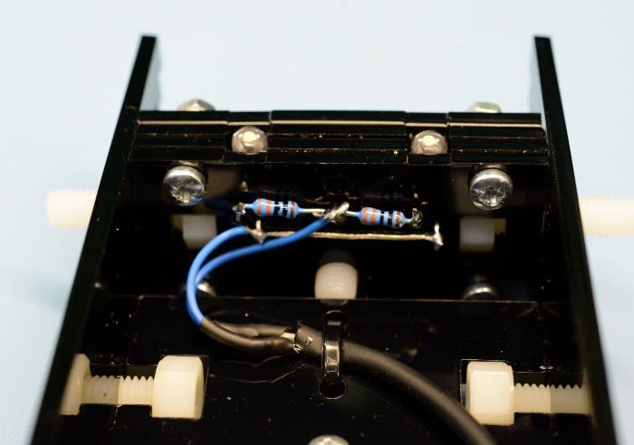
On the top panel and just to the left of the heatsink there is a 3.5mm jack socket. This is connected to 3.3v, GND and GPIO pin-4 on the Pi, with a DS18B20 sensor connected to these and a pull-up resistor between 3.3v and the GPIO pin. This allows for ambient temperature monitoring — or at least the temperature inside the case, which is likely to be a little higher.
A jack plug is inserted into the socket on the exterior and this is wired to an additional two DS18B20 temperature sensors. One of these will be inserted into a hole drilled in the heatsink and the other will be inserted into a hole drilled in the cold plate.
Together the sensors enable temperature monitoring of ambient, and peltier hot and cold sides.

At this point all we want to do is to get temperature readings from the three sensors and print this out to the terminal. A Python script was quickly hacked together for this purpose and we can move on to tidying this up and driving the LCD once we've confirmed basic operation.
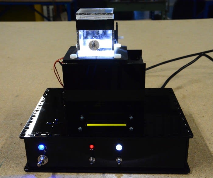
Chamber and lid

The chamber that sits on top of the cold plate is laser cut from four 2mm thick acrylic panels, capped with a square of 10mm thick acrylic — selected because it is heavier and should therefore sit more securely — that has a step etched around its side to help locate it and make a better seal.
A circular hole is cut in one of the panels so that a sample mounted on a wire and cork can be inserted. Just below the chamber lid is a band of black felt affixed to the inside.
Illumination

Above can be seen the chamber illumination. A neat solution that Stuart came up with, this is comprised of two wide angle white LEDs sandwiched between layers of acrylic, with a nylon screw at the top that together with a spring at the back allows the LEDs to to angled up and down.
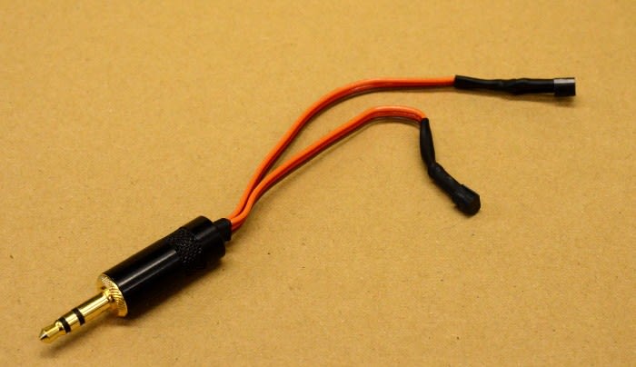
Resistors are wired to the underside of the LED assembly and a cable is terminated on the other end with a 3.5mm jack plug, which is in turn plugged in to the back panel.
Putting it all together

If we refer to the above diagram that Stuart put together for the first post. The aforementioned black felt will be our “alcohol wick”, soaked with isopropyl alcohol which will evaporate due to the relatively high temperature at the top of the chamber. Heat is removed from the bottom of the cloud chamber via the peltier thermoelectric module, heatsink and fan arrangement, causing a cloud of supersaturated alcohol vapour to collect there.
If all goes according to plan, when a charged particle passes through the cloud it should cause a trail to be left as the supersaturated vapour condenses out on the ions that are created along its path. Of course, this is provided that the bottom of the chamber is sufficiently cold, while the top — where the alcohol soaked felt is — remains warm enough to allow evaporation.
Initial testing

The felt was soaked with isopropyl alcohol and cooling turned on. Following which the temperature of the chamber cold plate steadily dropped as the heatsink warmed by a few degrees. When the cold side dropped to around -5C or so, a fine mist of droplets could be seen falling to the bottom.

After 40 minutes the cold plate had reached -20C and the temperature seemed to hold around this point. Just that bit short of our -25C target.
A very weak radioactive source that came supplied with a simple commercial dry ice cooled cloud chamber — intended for use in schools — was inserted. No trails could be observed, although an alcohol vapour mist could clearly be seen falling downwards (video best viewed in a higher resolution on YouTube).
Next steps

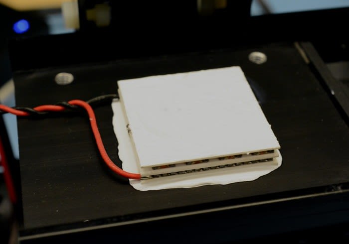
So, what could be done to improve performance? Well, as can be seen in the earlier photo of the cooler module, it looks as though perhaps too much thermal compound was applied! As can be seen above, there is also presently no insulation around the outside of module, located between the heatsink and cold plate, resulting in frost building up and very likely compromising performance.
Should cleaning off and re-applying thermal compound, together with fitting insulation, not deliver the desired improvement in performance, another option may be to increase the voltage supplied to the module a little. Although this would obviously mean that more heat is generated also.
Other possibilities include trying a different radioactive source, experimenting more with the lighting and applying an electric charge to the top of the chamber in order to clear old ions.
In any case, that we've initially succeeded in getting the chamber base down to 35 degrees below ambient, without using any dry ice etc. and just a compact solid state cooling system, feels like a reasonable achievement. With the fact that we have signs of a supersaturated alcohol vapour cloud forming in the chamber being rather encouraging also. More as the project develops!