Peltier cooled cloud chamber part 1
Follow article
 Dave from DesignSpark
How do you feel about this article? Help us to provide better content for you.
Dave from DesignSpark
Thank you! Your feedback has been received.
Dave from DesignSpark
There was a problem submitting your feedback, please try again later.
Dave from DesignSpark
What do you think of this article?
Cloud chambers are a basic form of particle detector that can be used to detect ionising radiation – invented by Charles Wilson, a Scottish physicist – in the early twentieth century. In this series of posts we will build our own cloud chamber with a combination of off-the-shelf and custom made parts, using a Peltier module (693-5075) for cooling and a Raspberry Pi (832-6274) for temperature monitoring.
This first post will cover the initial design and build, using DesignSpark Mechanical to draw a cooling plate in 3D, before exporting the model and milling it from aluminium. Other custom parts will be laser cut from MDF and acrylic.
Components
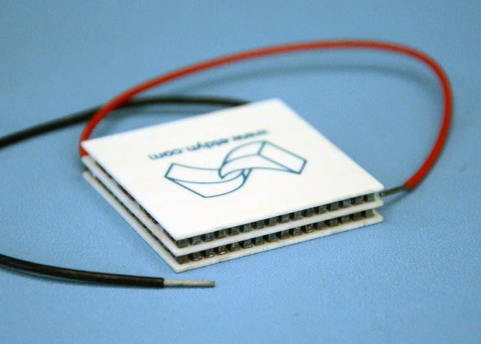
Peltier modules are thermoelectric devices that get cool on one side and hot on the other when a voltage is applied, and can be employed for either cooling or heating depending upon the application. They can also be used to create a voltage when there is a heat difference present across the two sides. They make use of the thermoelectric effect, further reading on which can be found on Wikipedia.
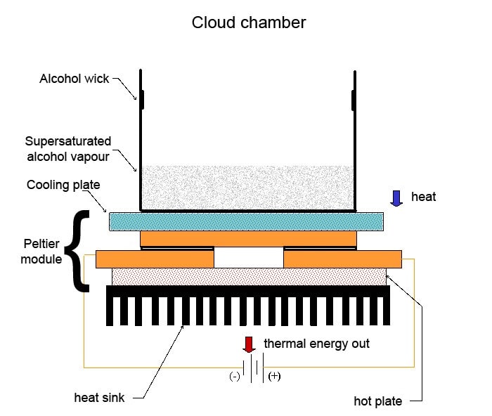
We will use a Peltier module (693-5075) to reduce the temperature of the cooling plate in our cloud chamber, with a large fan-cooled heat sink (189-8252) on the opposite side to remove heat from the system.
DS18B20 (540-2805) temperature sensors will be used to monitor the temperature of the system in three locations: the cooling plate, the heat sink and the ambient temperature. These will all be connected to a Raspberry Pi, with the readings displayed on a 16x2 LCD display (819-5119) .

Switches, inputs and outputs to the system will be housed in a custom enclosure, with bright LEDs positioned to illuminate the alcohol vapour trails within the cloud chamber.
Enclosure and heat sink

Whilst useful for housing and protecting the electronic components and wiring, the enclosure will also provide a sturdy base upon which to mount our heat sink and cloud chamber.
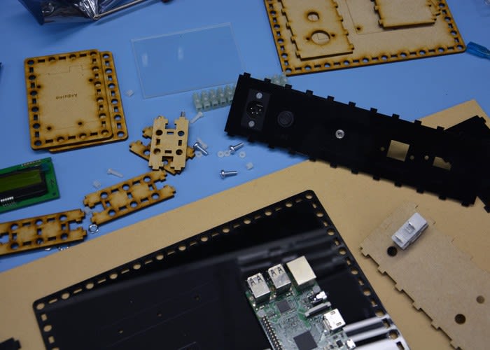
Rapid prototyping with a laser cutter allows for the design and construction of enclosures from sheet material at relatively low cost. A set of digital callipers were used to measure the stock parts chosen for our project, providing dimensions for mounting holes and cut-outs.

MDF sheet stock is cheaper than acrylic and useful for testing revisions of a design before committing to more expensive stock material. It can also be cut to make sizing and positioning jigs. The photo above shows a simple jig to aid the marking out of holes to be drilled in the heat sink.

Once centre punched and drilled, these holes were tapped with an M6 thread to accept nylon bolts to secure our Peltier device and cooling plate to the heat sink. Nylon hardware is used rather than steel to minimise heat transfer between the hot and cold sides of the Peltier device.

An 80mm fan (492-4449) will be used to cool the heat sink. Rather than drilling and tapping further mounting holes, double sided adhesive foam was used to attach the two and give some mechanical isolation between the fan and the rest of the assembly. This foam was also used to attach acrylic sides to the heat sink, forcing all of the air moved by the fan over the cooling fins.

With the fan and heat sink mounted to the top plate of the enclosure, the Raspberry Pi and other electronic components were fixed into place as required. A simple power distribution circuit will be soldered up to give 5V to the Pi and 12V to the Peltier device.
Fabricating the cold plate

A cooling plate was modelled in DesignSpark Mechanical. Ideally this plate will be as stiff as possible, so the model was designed to suit the thickest stock we had to hand, a 10mm thick piece of aluminium plate.
Since the cooling plate will be held in position by an acrylic collar, a lip was added to the top surface of the model to ensure a good fit and prevent any lateral movement.
Once the design was completed it was exported as an .stl file, a common 3D model format.

It is not possible to feed a design file directly into a CNC machine, press 'go' and wait for your part to be made. There are several steps involved that will differ according to the software and machine used, as detailed in another post. Put simply, the design file needs to be converted into toolpaths and then a series of instructions for the machine to follow, most commonly as G-Code.
A piece of software called CamBam was used to convert the DesignSpark Mechanical model into toolpaths. It is free to try and easy to use, with great documentation and a large community of users. Since the part was going to be machined from a larger sheet, holding tabs were added within CamBam to make sure the part stayed in place after the last cuts were made. This prevents damage to the workpiece and milling machine that could occur if the part came loose.

Once satisfied with the toolpath created within CamBam, it was exported as G-Code. Though one can get a good idea of the toolpath in the visualisation window in software like CamBam, using another piece of software to simulate the exported G-Code can highlight any errors you may have missed.
Simulation can save material, milling bits and time, making it worth the extra effort before running G-Code on your machine. Another free-to-try software was used, CutViewer Mill, shown in the screenshot above.

Happy with the simulation of the G-Code, we were ready to commence milling. The photo above shows the workpiece clamped to the bed. Before the main G-Code was loaded and run, a separate file was loaded to face mill the surface of the material.
Face milling is a process whereby a small amount of material is removed from the workpiece, removing any imperfections and leaving a smooth, flat finish. Once the workpiece was faced, it was flipped over and clamped back to the bed with the faced surface down.
The main G-Code was then run and the cooling plate milled as shown in the video above. The holding tabs kept the plate in place, meaning that some hand finishing was required to remove the part and these tabs. Though the finish looks bumpy or patterned it is in fact quite smooth to the touch.

We now had a cooling plate with a smooth, flat top and bottom as well as a lip around the edge. It was washed and degreased before being painted with satin black paint. This will reduce reflections and provide contrast to view alcohol vapour trails when the cloud chamber is operational.
Next steps

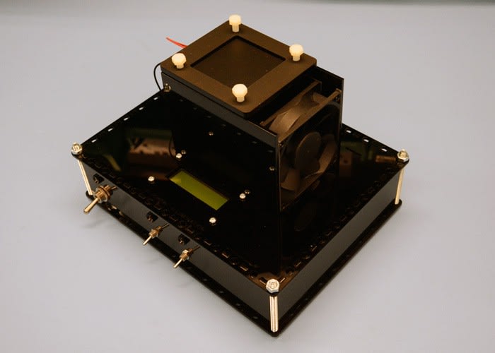
Once the paint was dry the plate could be put together with the rest of the cooling parts. Thermal paste (217-3835) will be used between the faces of the Peltier module, the heat sink and the cooling plate to ensure optimum thermal transfer between each component. However as there are still some parts to add, including the chamber itself, the paste was not used right away. Instead the parts were put together in a dry run to check the fit.

In the next post we will add the final mechanical parts before covering the wiring and electronics. Operation of the cloud chamber will be explained in more detail, the Pi configured and tests carried out to see how well it all works!