Controlling a Pedestrian Crossing with Structured Text and a RevPi Core 3
Follow article
 Dave from DesignSpark
How do you feel about this article? Help us to provide better content for you.
Dave from DesignSpark
Thank you! Your feedback has been received.
Dave from DesignSpark
There was a problem submitting your feedback, please try again later.
Dave from DesignSpark
What do you think of this article?
A Structured Text (PLC) program that builds on our previous traffic lights example to build a solution for controlling a pedestrian crossing
Having simulated a simple set of traffic lights in my last blog post on using the Kunbus RevolutionPi programmed with Structured Text using LogiCAD 3, I decided to try developing my traffic light project into a pedestrian crossing. This would involve adding an input in the form of a button for the pedestrian to press to trigger the traffic lights, plus an additional output for a crossing indicator. For extra authenticity adding a buzzer to warn the pedestrian that the traffic lights were about to change back to green and it is therefore no longer safe to cross.
Hardware
Once again I’m using the RevPi Dore 3 and with a DIO for I/O, mounted on DIN rail fixed to a piece of laser cut 5mm MDF. In addition to the existing setup, I now needed to supply 24V to the DIO input terminals power, making sure they connected correctly by referring to the How to Connect the Power Supply section of the quick start guide.

They connect to the X2 connector on the DIO Module – 24V to pin 1 and Ground to Pin 2.
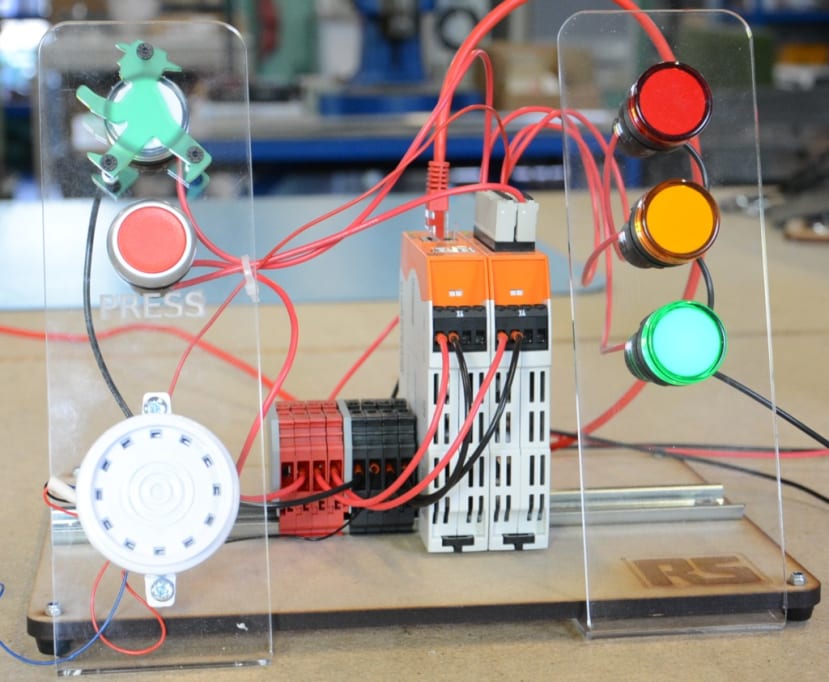
The pedestrian crossing light, a white LED indicator (763-7905) , and a buzzer (626-157) were connected to DIO Module Outputs 4 and 5 respectively. Then the button was connected to Input 1 - taking note that the inputs are numbered from the bottom right-hand corner of the connector and 24V. As the Inputs are receiving 24V from the power supply, I had initially assumed that one side of the button should connect to ground, but after re-reading the Getting Started Guide and this forum post, I realised that it should be connected to 24V.
I next cut and bent a simple acrylic mount for the pedestrian components — button, buzzer and white LED — adding an East German-style green man to go over the LED for fun.
Settings
The next job was to give the new components friendly labels in the RevPi’s configuration settings. This means using the Value Editor section in PiCtory and making the corresponding alterations to the global settings file in LogiCAD 3.
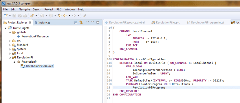
To do this from LogiCAD you can right-click RevolutionPiResource under Revolution Pi in the Project Manager and then click on Change IO Configuration. This will open the PiCtory page in your default web browser.

Edit the Inputs and Outputs in the Value Editor section in the bottom right-hand corner of PiCtory. I Changed Output 4 to “Cross_4” and 5 to “Buzzer_5”. I then changed Input 1 to “Button_1”.
Then save by clicking File and selecting Save as Start-Config.
Back in Logi.Cad 3 now right -licking on RevolutionPiResource again and then selecting Load IOConfiguration, will fetch the configuration file from the RevPi and update the Global Settings file in the LogiCAD 3 Project accordingly.
The ST Code
PROGRAM RevolutionPiProgram

	VAR
	wait : TON;
	count : INT;
	END_VAR

	VAR_EXTERNAL
		Red_1 : BOOL;
		Amber_2 : BOOL;
		Green_3 : BOOL;
		Cross_4 : BOOL;
		Buzzer_5 : BOOL;
		Button_1 : BOOL;
	END_VAR

CASE count OF
	0: //init
		count := count 4;


	1: // Amber

   		Red_1 	:= False;
   		Amber_2 := True;
   		Green_3 := False;
		Cross_4 := False;
		Buzzer_5 := False;

   		wait(IN:=TRUE, PT:=T#7s);

   		IF wait.Q THEN
   			wait(IN:=FALSE);
   			count := count + 1;
   		END_IF;

   2: // Red and Cross

		Red_1 := True;
		Amber_2 := False;
		Green_3 := False;
		Cross_4 := True;
		Buzzer_5 := False;

		wait(IN:=TRUE, PT:=T#10s);

		IF wait.Q THEN
			wait(IN:=FALSE);
			count := count + 1;
		END_IF;

   3: // Red, Amber and Buzzer

   		Red_1 := True;
		Amber_2 := True;
		Green_3 := False;
		Cross_4 := False;
		Buzzer_5 := True;

		wait(IN:=TRUE, PT:=T#5s);

		IF wait.Q THEN
			wait(IN:=FALSE);
			count := count + 1;
		END_IF;

   4:  // Green
		IF Button_1 = FALSE THEN count := 1;
		END_IF;

		Red_1 := False;
		Amber_2 := False;
		Green_3 := True;
		Cross_4 := False;
		Buzzer_5 := False;

		ELSE
		count := 4;

END_CASE;

END_PROGRAM
At the start of the code the variables are set:
VAR_EXTERNALThe External Variables need to match exactly the labels for the Inputs and Outputs set in PiCtory and the Configuration file in LogiCAD 3.
Then the instruction:
count := 4;Sends the program to the block of statements labelled number 4. These statements first check to see if the button is pressed, if it is not then the green light is turned on and all the other lights and the buzzer are turned off. Being an ST program it runs in a loop and so returns to the beginning and does this again. The result is that the green light stays on unless it detects the buttons is pressed, in which case it goes to the of statements labelled 1 and then runs through the sequence.
There is a timer in each block:
wait(IN:=TRUE, PT:=T#5s);So the time that each step of the sequence runs can easily be adjusted by editing the value after the T# . In this example it is set at 5 seconds - 10s would be 10 seconds and 10ms 10 milliseconds.
Although it is not necessary, I include the value for each variable in every block of statements as that makes it easier to see and, if necessary edit, what happens at each step of the process.

Once LogiCAD 3 had connected to the RevPi and the code has been built and uploaded, the lights, button and buzzer behaved as expected.
Potential
This example is a simple sequence of events with only 4 steps but it could easily be added to with more outputs and/or different combinations of outputs, running in sequence at different durations. This means it could be simply adapted to trigger all sorts of lights, buzzers, motors or whatever, and further developed by adding inputs such as temperature or motion sensors.