What is the blend tool and how do I use it?
Follow tutorial
 Dave from DesignSpark
How do you feel about this tutorial? Help us to provide better content for you.
Dave from DesignSpark
Thank you! Your feedback has been received.
Dave from DesignSpark
There was a problem submitting your feedback, please try again later.
Dave from DesignSpark
What do you think of this tutorial?
This tutorial requires:
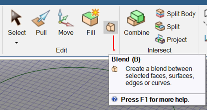
DesignSpark Mechanical V6.0The blend tool allows you to create new geometry between points, curves, surfaces, and solids. It can be used to make a smooth transition between objects, and to repair or replace troublesome areas of your design. The blend tool is located under Design->Edit options.
Creating a blend
To create a blend:
- Enter the Blend tool
- Select a point, edge, or face
- Ctrl + Select a corresponding point, edge, or face
- You can select more than two objects
- The blend is previewed as you select
- Complete the blend
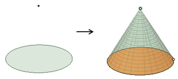
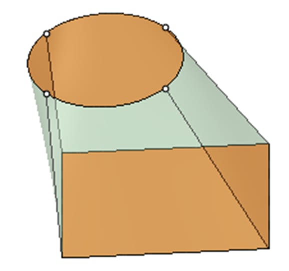
You can blend both closed and open sections to a single point as shown below.
Blend tool options
The following options are available in the Blend tool Options panel when you select the appropriate geometry for a blend.
- Rotational blend: Create cylinders and cones whenever possible during the creation of a blend. You must have selected faces, points, or edges that can be rotated around a common axis.
- Periodic blend: Go all the way around when blending. The blend will begin and end at the first selected object. You must have selected three or more faces, points, or edges that can be rotated around a common axis, and that also span an arc greater than 180 degrees. (Blending between 3 equal-radius circle faces creates a torus.)
- Ruled sections: Create straight edges when you blend. When you blend between faces, this option has the same effect as selecting the face and its edges.
- Local guides: Selected guide curves only influence areas near to them.
- Clocked guides: Guide curves are oriented relative to the face edges instead being simply translated from vertex to vertex.

- Normal to Centerline: When on by default, Normal to Centerline forces the Blend algorithm to keep sections normal to the centerline. When off, the algorithm has more freedom to adjust sections so that a surface can be created.

- Show UV grid: This option is ON by default to help visualize contours by displaying a grid on the preview. Use the dropdown slider to increase or decrease the density of the grid.
When blending between coloured objects, the blended geometry takes on the colour of the object that was selected first.
Examples
Now, let’s show you a few examples.
1. Basic use with guide curves:

2. The bow section of a boat hull:
3. The nose cone of an airplane:
4. Fitting varying curved profiles on the same face (alternative to PULL and SWEEP):
