How do I create a new model from schematic?
Follow tutorial
 Dave from DesignSpark
How do you feel about this tutorial? Help us to provide better content for you.
Dave from DesignSpark
Thank you! Your feedback has been received.
Dave from DesignSpark
There was a problem submitting your feedback, please try again later.
Dave from DesignSpark
What do you think of this tutorial?
This tutorial requires:
DesignSpark Circuit SimulatorThis tutorial shows how to create a new simulation model from a schematic. This allows you to conveniently design a circuit or system, and then encapsulate it as a component that can be used in other circuits or systems.
In this tutorial, you will create an electrical resistor model with built-in series inductance. This effect can be realized by placing a resistor and inductor in series on a schematic, and saving the resulting "circuit" as a model. Encapsulating design functionality into a model in this manner can be quite useful - both to simplify an otherwise complex "flat" design, or to reuse functionality in multiple designs.
Create a simple R-L design
The following steps show you how to create the design and save as a model.
1. In the Design Analyzer's Component Browser, locate and drag both a resistor and inductor component onto the schematic.
These components can be found in either the My Favorites or Analog Electronics categories, or use the search box directly.
Since the goal is to create a model, you will not attach sources/loads in the design at this time. However, it is often. useful to do so temporarily to first test the desired functionality before generating a model for it.
2. Connect the resistor and inductor in series as shown below.
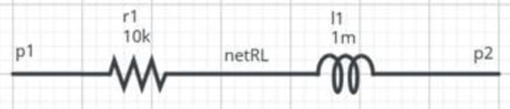
3. Set values for resistance_value and inductance_value on the resistor and inductor, respectively.
The figure shows 10k for the resistor and 1m for the inductor.
4. Name the nets as shown in the figure.
Generate a model and edit
Model generation is automatic, but you will need to edit the model to expose pins and possibly properties. You will see how to do both below.
Generate the model
1. Click on the Create new component button in the upper-left region of the application and select: From Schematic.
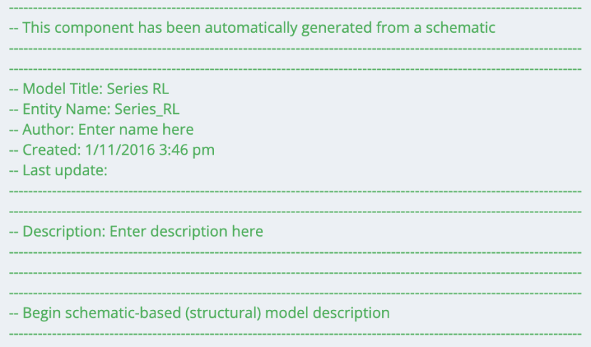
An informational dialog will be displayed with some tips for schematic-generated models.
2. Click on the Click here to generate model button.
A VHDL-AMS model will be automatically generated for whatever is currently displayed on the schematic, and it will be loaded into the Component Editor.
Note: Before the model is generated, a copy of your design is silently made so the original design will not be saved.
3. Click on the Save new component button to name and save your new model to the database.
4. Type in a model name when prompted and click OK.
This name does not need to match the name of the design/schematic. The name "Series RL" was chosen for this example.
The Symbol Editor will also be displayed. You will work with it shortly.
5. Your model should look similar to the following.
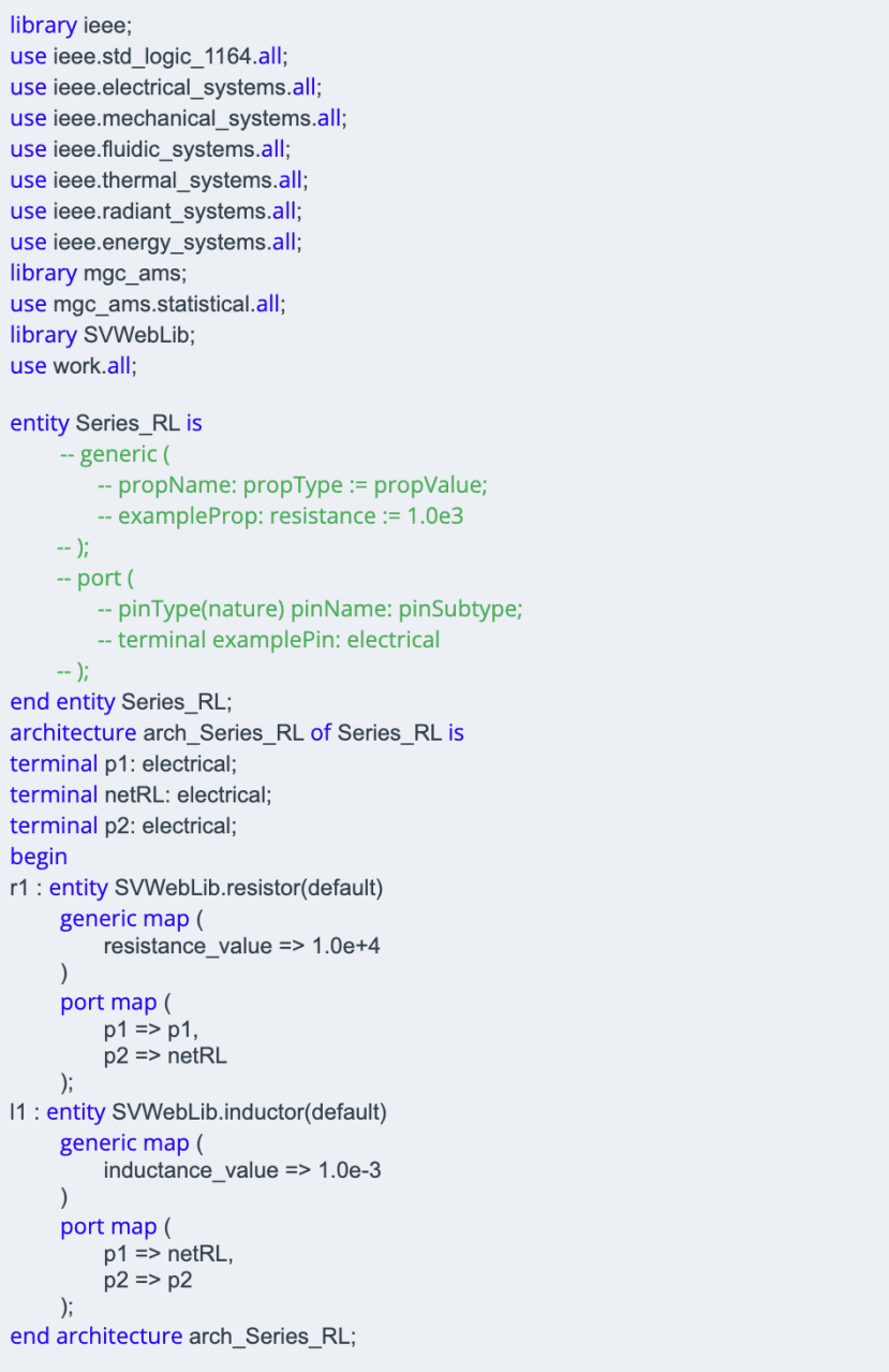
There are a few things worth noting in this model:
The net names you supplied (or defaults if not) are used to establish the connectivity between components. For example, you can see that pin p2 in the port map section of the resistor connects to netRL; pin p1 in the port map section of the inductor also connects to netRL, as expected.
The three nets are internally declared at the top of the architecture section. This means that these nets are not visible outside of the architecture.
Both generic and port sections have been included in the generated model, but are commented out by default. These are there so they can easily be "uncommented" and used as necessary, as you will do shortly. There are also commented examples of how these sections are used. These are for information only and may be removed if desired.
Add pin connections
Then you add pin (i.e. port in VHDL-AMS) connections for the model. This is done by replacing internal net declarations with entity port declarations. In this example, we would like p1 and p2 to be pins for the model, and keep netRL internal to the architecture.
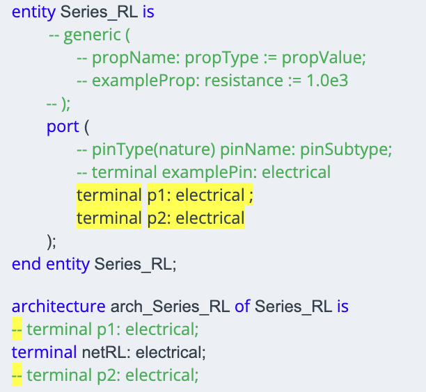
1. Change the model as indicated below:
a. Uncomment the beginning line for the port section ("port (").
b. Uncomment the ending line for the port section ("),")
c. Comment out the terminal p1:electrical and terminal p2: electrical lines at the beginning of the architecture.
These will normally just be removed from the architecture section, and are only left as comments for instructional purposes.
d. Copy the terminal p1: electrical and terminal p2: electrical lines into the port section.
Pay special attention to the semicolons ";" - the final semicolon appears after the closing parentheses of the port section, rather than directly after the last terminal declaration.
2. Bring the Symbol Editor to the front.
The pins you added to the model were automatically placed on the symbol, and now you will reposition them to make the symbol more aesthetically pleasing and easier to use.
3. When the Symbol Editor comes up, drag the pins to the locations shown below.
Pin p1 should be on the left and p2 on the right.
4. Click the Save button in the Symbol Editor then close it.
Note: When you click Save in the Symbol Editor, the symbol is written to the Component Editor. To store symbol updates in the DesignSpark Circuit Simulator database, you always need to save the Component Editor after your Symbol Editor edits.
The component can now be connected into a design and used like any other component. However, you will first update the model to allow properties to be passed into it from the schematic.
Allow properties to be passed from the schematic into the model
As it now stands, the value of the resistance_value and inductance_value properties are fixed to what you specified in the original design before generating the model (20k and 1m in this example). Next, you will see how to update the model so these values can be specified at the schematic level by the user and be passed into the model. These properties are referred to as "generics" in VHDL-AMS.
As you did with the port section previously, uncomment the beginning and ending lines for the generic section.
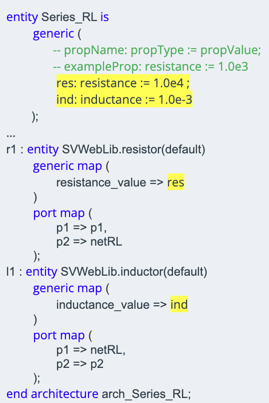
Add in the indicated properties and reference them as shown in the abbreviated listing below.
The values that are assigned to resistance_value and inductance_value are now given property (generic) names, res and ind, respectively.
Again, pay special attention to the semicolons ";" - the final semicolon appears after the closing parentheses of the port section, rather than directly after the last terminal declaration.
Properties can optionally be given default values as shown below so the model will still simulate regardless of whether or not the user supplies values to them in the schematic.
Note: When adding property values directly in a model, you must adhere to VHDL-AMS syntax. SI unit prefixes (like "m", "u", "k", and so forth) are not supported inside the model. For example, "res" is specified inside the model as "1.0e4" rather than "10k".
Complete schematic-based model
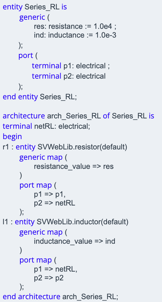
The model should now be complete. It includes pin declarations as well as property values that can be passed in from the schematic. The final entity/architecture of the model is shown below. Inline "instructional" comments have been removed.
Create and verify model
Now that the new schematic-based model is complete, you should verify its functionality. The easiest way to do this will be to instantiate it along with discrete resistor and inductor components wired in series, and then verify that they yield the same simulation results.
You can just use the original design from which you generated the model as a starting point, and drag out an instance of your new model from the My Components category of the Component Browser.
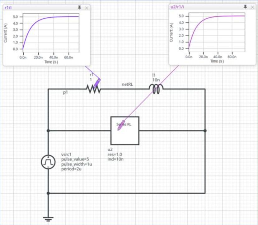
This has been done below. New values of 1 and 1n were selected for the resistor and inductor to verify that they are correctly passed in and will overwrite the default values of 10k and 1m.
As you can see, the time constant for the series current is the same through both the discrete resistor and the resistor instance in the new model.
Summary and additional notes
This completes the tutorial. See the Component/Symbol Editor Help for links to resources for both the modelling tools as well as general VHDL-AMS modelling instructions. Some additional notes regarding schematic-based models are given below:
- If your design includes custom models that you have created, those model listings will be copied into the top of the generated model.
This allows the generated model to access any required custom model, and also allows the generated model to be self-contained and portable.
Note: The top-level schematic-based model will always appear at the bottom of the model listing.
- Schematic-based models can be nested.
You can create a schematic-based model and use it in a design that is then also saved as a schematic-based model.