Design of an Analog Car - Remote
Follow article Dave from DesignSpark
How do you feel about this article? Help us to provide better content for you.
Dave from DesignSpark
Thank you! Your feedback has been received.
Dave from DesignSpark
There was a problem submitting your feedback, please try again later.
Dave from DesignSpark
What do you think of this article?

In order to improve the laboratory of EE2109 of City University, we are requested to combine and design a new laboratory of it. In EE2109, students will learn about transistor, operational amplifier, diode, and filter. To combine these technologies and design a interesting laboratory, we decided to design a basic simple Analog Car circuit.
Design:
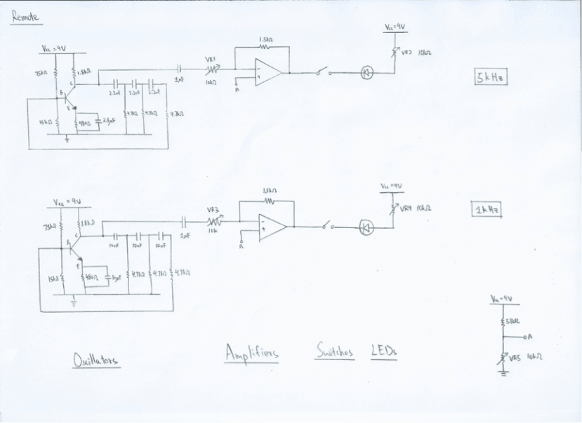
For a basic Analog Car, it should have two wheels that controlled by two signals. Therefore, we only need two things and they are signal emitter and receiver. In the following, we first focus on the signal emitter – Remote.
For a signal emitter – Remote, we need to generate two signals that controlling two wheels to on or off. For example, we use LED bulb as an emitter, then what we need is an oscillator to generate a frequency and emit though the LED bulb. Besides that, we need an amplifier to ensure the signal emitted is strong enough or not. Therefore, we need to have two sets of this to control two wheels on or off.
Material List:
|
RS part number |
Manufacturer |
Manufacturing number |
Description |
Quantity |
|
522-2693 |
Bourns |
3386P-1-103LF |
Variable resistor 10K
|
4 |
|
479-1390 |
TE Connectivity |
FSM2JH |
Switches
|
2 |
|
761-3546 |
Fairchild Semiconductor |
LM358N |
IC |
1 |
|
773-3996 |
Vishay |
TSUS5202 |
IR LED |
2 |
|
787-4864 |
C & K |
OS102011MS2QN1 |
Power switch |
1 |
|
744-2202 |
RS |
744-2202 |
9V Battery |
1 |
|
|
|
BC109 |
Transistor |
2 |
Breadboard:
To check whether it is work or not, we first need to test it on a breadboard. We put all the components, the output is different from what we expected. There are some errors exist. After debugging it, we added some variable resistors to control the voltage gain. Also, we set up a virtual ground to separate the signal ground and common ground.

Schematic:
After a first test on the breadboard, we try to draw the schematic of the circuit on computer. By using the design spark PCB, we can find most of the components from its powerful libraries. However, some components such as variable resistor and battery holder do not exist in the libraries. Then, we can use its model source function. This function enables us to search some components online and directly put them into the design spark PCB. Moreover, we can draw the components by us in design spark PCB.

PCB
Using the Design Spark PCB again, we can convert the schematic to PCB layout. What we need to do is print the layout and buy a copper board. After the PCB fabrication, we can start to drill the hole for components and double-check the copper routes.


>Conclusion<
If you are following what we did before, you will get two perfect 5kHz and 1kHz signals emitter. However, if you want to design your own circuit, you can modify it to become yours. Design to enjoy, enjoy your designing. Thank you.
This article is only including the remote part of the Analog Car. For the car body part of the Analog Car, you may refer to another article.