
はじめに
ソフトウェアのダウンロード、インストール、ログインの方法
初級、中級、上級に分かれたステップバイステップのチュートリアルです。
ソフトウェアのダウンロード、インストール、ログインの方法
ソフトウェアのインターフェースや基本操作を学びます
"初めて3Dデータを作成するための手順を学びます。

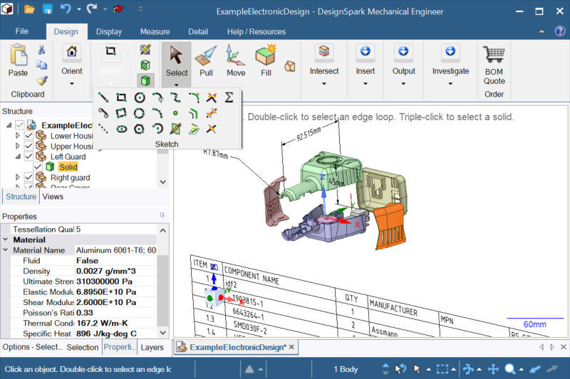
オンラインライブラリから部品の3Dモデルをダウンロードする方法を学びます。
ソフトウェア内の機能を駆使して作成したい3D形状に仕上げていく方法を学びます。

作成した3Dデータを3Dプリンタで出力するための方法を学びます。

マルチシートライセンスなら、開発チームのライセンス管理が容易になります。
DesignSpark Mechanicalのユーザと相談できるコミュニティーです。多言語混在コミュニティーなので日本語でも投稿頂けます。
With a Creator or Engineer subscription, DesignSpark Circuit Simulator allows your simulations to run longer than 1 minute and upto 1 hour of server compute time.
Our Circuit Simulator was introduced last July and can be a good tool for DS PCB users, and we know that some of our DSM users also do PCB designs...
We list some key reasons why you may need an extended simulation time:
Run electro-thermal transient simulations long enough for temperatures to reach steady-state, to verify reliability under real world operating conditions.
Allows compute-intensive simulations, such as switching power electronic circuits, to run as long as necessary for line and load transient response tests.
Monitor the behaviour of critical components to varying inputs over an extended time period, such as for vehicle drive-cycle simulations.
Check it out at https://www.rs-online.com/designspark/designspark-circuit-simulator
表題の件、1度目はできたのですが、2回目からは下記のようなポップアップがでてダウンロード出来なくなりました。解決方法はありますでしょうか?
記
Demonstrating the powerful but unusual edge and face rounding that DesignSpark (Parasolid) has... REJOICE !
Alternatively, pull two edges a small way, then pull in opposite direction to make a full round.
and for circular rounds, select two edges , pull to create a round on each edge a little, then pull in opposite direction.
To remove the full round, select and Fill.
This also works for eccentric round edge pulls as below gif:
Other tapering helical multi-sided with rotational sections are easily made with DSM if needed.
会社のデスクトップでCreatorを、出先のノートパソコンでExplorerを、一つのメールアドレスで使うことができません。どちらかがストップします。併用すること不可能ですか。 「ビュー」など、種類の文字が「作成」欄により半分書けてしまう。 インストール後に登録の間にエラーが発生しました。が発生し開かない
再インストールでも同じ改善できない Have bought a new computer and downloaded software for PCP and mechanics.
But when I start these programs, I should start by logging into my account.
But I can't login to DisgnSpark " to any of my accounts.
I receive information that I am unauthorized.
(Even made a new account to see if something went wrong with the account.)
I have downloaded and reinstalled a couple of times without the login working.
I haven't had any problems on the old computer.
However, the software remains on the old computer and works on it.
What do I need to do to access my account from the software? Why do the "Views" alway stay at zero on the topics posted here on DSM? It would be useful to see how many people are viewing certain topics. Just curious if that is turned off on purpose or is a bug or a glitch. Whether I am logged on or off they are always showing "0" views on all topics.
Thanks Molded or Formed parts need a minimum draft to allow parts to extract from shaping tools such as plastic injection molds, pressure / gravity die castings, formed metal pressed sheets. Understanding and being able to design using the necessary draft angle is part of being an Industrial designer or anyone involved in specifying manufacturing information.
Either analyse your own designs or Import supplier models and check the draft before commiting to any manufacture.
DesignSpark Mechanical has a draft dynamic analysis tool in the Measure Tab and I think it's superb.
Example part:
Tube of varing profiles made by blending layout constrained sketches to tangential (red face) and conic 2.5 draft angled face. (blue face).
Using the new Mirror tool or duplicating the curves to make a continuous section, other faces can be made.
Analysis can be made on a singular face or the complete shape.
For example, the draft has been set at 3 degrees; with the direction of draft specified using this arrow:
and choosing the plane shown, a white arrow direction is drawn ( see 2nd above image - arrow in left hand bottom corner).
With 'Both directions' also selected, any face about the specified direction that is not at least 3 degrees will be shown in the user specified or default color - here shown in red.
The part was designed with 2.5 draft.
Changing the check value to 2.51 the result is shown below.
Changing the check value to 2.5 the result is shown below.
Probing can be singular or multiple points:
Transition values will show the gradient of draft. With 1 % transition from a 2.5 degree start, all areas upto 2.58 degrees are shown in red.
Draft angle dynamic dragging:
Whole part analysis.
Shadow Lines can be shown and created:( rename as appropriate ) Shown is a 3 degree shadow line.
Enhanced shaed part with drafting plane.
In the design of a Diecast car wheel shown below, the model creator ( me ) forgot to add draft to the wheel rim - whoops!
Manufacturing errors created by inadaquate design; even even small ones, cost time and money to fix and reputation is lost!
On the wheels rear, all the ribs that create the hollows also need the draft checking. The part will shrink during molding and may shrink tight on any inadquately drafted faces causing part ejection problems.
Again , there are more small area's that are less than 3 degrees. ( 3 degrees isn't the standard for diecast - it will depend upon material and texture ( texture not usually applied to diecast parts) - advice is to always seek experienced manufacturer advice).
Finding small areas like this would be impossible without an analysis tool:
Ask if wanting additional information. It's a simple thing really, although I've used DSM for years it's always bothered me. When I start a new design I get this:
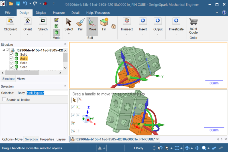
But I want Z pointing up X pointing to the right and Y pointing backwards. This way It's the correct way around for the slicer. I know I can work around this but it's always bothered me. Don't be too hard on me Hey out there.
I have this odd problem I can't seem to get around.
I import a spline from a DXF file, created by any app on my pc, the problem occurs.
If I click on the spline and try to fill it. Nothing happens. However if I alter the spline in anyway, move it rotate it...anything. Then try to fill it. It deletes.
This is a repeatable problem. Whats even stranger is I can export a series of splines all exactly the same (copies of each other), but one or two will not work, if it's a series of 10 splines in a row, the 3 and 4th might act up and the rest are fine. If I reExport the same series of splines as a DXF it's always the same objects that delete. The rest are fine.
I suspect an issue with the import engine in some way.
I have no work around at this point. Are there any plans for DS to implement .3MF exports? I use designspark for creating 3D printing models with multicolor printing. .3MF exports are very necessary. Please tell me this in the works and will be released soon.... Ich kann die oben genanten Formate nicht importieren. Die Version ist 6.03 und ich bin bei rs-online angemeldet. Was läuft hier falsch?
Vielen Dank! See more of the information you need, with DesignSpark Creator and DesignSpark Engineer
Product data, environmental and lifecycle information as well as 3D models, footprints and schematics for a billion products - more info here:
https://www.rs-online.com/designspark/product-design-centre
Ok, on my switch project I was getting along fine and thought I could make the whole thing without asking for help. But, although I can easily make this spacer without the splines in the form of cones or straight cylinder shapes using the revolve tool and it will likely work fine, I was wondering how I could make it look like the original. I have added a pic of the spacer and would like to know the best approach or steps to make this odd piece that will be 3D printed likely with supports. I just need a little guidance. :)
I am thinking make and extrude the circle in the center then add a sketch shaped like a plus sign and extrude it for the left side. Then add another sketch for the right side but it has a step there, so make the short section and add yet another sketch to finish the right side?
Thanks in advance!
What does more than 1 minute of simulation time allow you to do?
3Dモデルのダウンロードができない。
Pull Rounds in DSM v6 - standard radical functionality available to all.
複数のパソコンで使用する
パネルの種類文字をきちんと見たい
開かない 登録の間にエラーが発生しました。
Unable to activate Mechanics and PCP software by logging into my account
Forum question
Analysing Draft angle - How it works
Default XYZ orientation
Spline keeps deleting.
.3MF export
Creator Version, kein Import von dxf, dwg, stl oder step möglich
What is the DesignSpark Product Design Center?
Best way to model this part?