Wireless Power Transfer System for Rehabilitation
Follow article Dave from DesignSpark
How do you feel about this article? Help us to provide better content for you.
Dave from DesignSpark
Thank you! Your feedback has been received.
Dave from DesignSpark
There was a problem submitting your feedback, please try again later.
Dave from DesignSpark
What do you think of this article?
Introduction
This project details how to build a wireless power transfer system using an inductive link for the rehabilitation of a patient with disabilities of the arm, shoulder and hand.
The system is composed of 2 major parts - the transmitter and receiver. The transmitter generates the magnetic field to deliver electrical energy to the receiver. It is also able to navigate the receiver and perform training on the physical movement of the receiver. The receiver is battery-less, wireless and lightweight. The receiver's power supply receives the inductive power generated from the transmitter side coil. This wireless power transfer system is a tool to help, train and record the rehab process of the patient. By using this wireless power transfer system, patients are able to rehabilitate in a convenient and interesting way.
Instead of using an infra-red sensor or motion camera, we used this inductive link wireless power transfer system so that the system will not be easily affected by the environment, and it is also able to detect the 3D position and the angular alignment of the receiver. The infra-red sensor will be easily affected by the angle alignment.
When the receiver is placed in different positions above the transmitter, the impedance, voltage and current of the transmitter coil will change according to the distance between the two coils. And when we adjust the phase difference of the current through the transmitter coils, the resultant magnetic field will change to a different angle, transferring the power in a different angle.
Theory Behind

There will be a magnetic field generated when a current (I) passes through a coil.

The upper coil is the transmitting coil. The bottom receiving coil receives the inductive power generated by the transmitting coil.
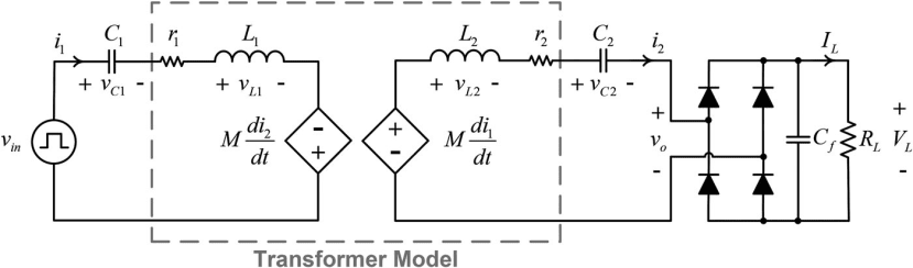
The system can be drawn into the diagram as shown above. Since the coil is not perfect, there is a resistance (r) within the coil. And L1 and L2 are the self-inductance of the coils, M is the mutual inductance. The transferred power is basically based on the value of mutual inductance (M), the rate of change of current and the self-inductances (L) of each coil. There are also resonate capacitors (C) for each coil.
In particle condition, the transferred power also depends on the lateral misalignment, displacement and the angular alignment between the transmitting coil and the receiving coil.
Basic Structure
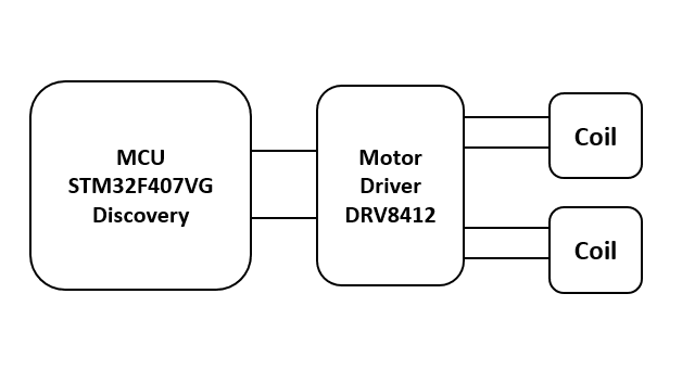
At the transmitting coil side, an MCU and a motor driver are used. The basic structure of the transmitting coil is shown as above. The reasons for using the motor driver are discussed in part 2 of the article where we develop the first prototype.