Which type of PCB should I use in my design?
Follow articleHow do you feel about this article? Help us to provide better content for you.
Thank you! Your feedback has been received.
There was a problem submitting your feedback, please try again later.
What do you think of this article?
When thinking of your design, one of the fundamental questions will always be what type of printed circuit bord (PCB) is needed. Each type has advantages and different cost effects.
Some of most important things to bear in mind are:
- Price
- Size & Fit
- Application
The decision you make will be based on the order of importance of these parameters.
If price is the important factor in your design, it is important to remain within the most typically used technologies. Price is determined by ease of manufacture and also by whether the materials and technologies chosen are commonly used by manufacturers. The higher the volume produced, the cheaper the cost of each individual board.
Price
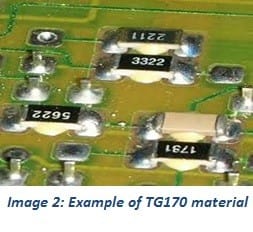
For more information in how Rigid PCBs are made take a look at a blog we made earlier - What is a Printed Circuit Board?
The most common, and thus cost effective, material is FR4, this glass fibre epoxy laminate. FR stands for flame retardant and has a max ambient temperature of 120℃ and 130℃.
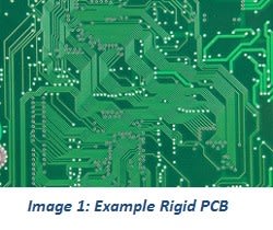
Other materials such as TG170, TG150 and CEM can be used for improving characteristics such as thermo-mechanical properties. For example; TG170 is used when the heat dissipation of a component is higher than normal electronic components.
Size & fit
To reduce the rigid circuit thickness, material thicknesses between 0.8mm to 1.6mm can be used. Again, the less common the usage, the higher the price.It maybe necessary to reduce the size of the PCB to fit into a smaller housing. This can be done by increasing the layer count and created connections (vias) between the layers.
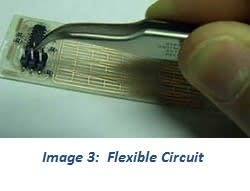
Flex circuits are used in consumer devices, automotive applications and others where space and flexibility are important.
Other advantages include
- Weight
- Increased heat dissipation
- Faster assembly
- Cost specifically in high volume use
Disadvantages to flex circuits include
- Increased cost in initial design – in prototype volume they can be expensive.
- Very difficult to repair a damaged circuit
- Prone to damage by inexperienced operators
Originally, these boards were developed for military use. As laptops became more popular, companies such as Compaq started to use them more. They are a combination of flex layers with a number of rigid boards internally or externally. Typical nomenclature is 2F6R – 2 layers of flex and 6 layers of rigid boards.
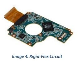
Rigid-Flex is commonly used in many industries today to
- Reduce space needs.
- Cut costs in larger volumes by eliminating expensive connectors.
- Decrease weight due to connectors and less rigid layers.
- Increase reliability by reducing connectors and solder joints and can increase reliability.
- Reduce cost in assembly pricing.
- Simplify test conditions.
This EDN article by David Read explains in detail the cost advantages to Rigid Flex.
These advantages must be weighed up with the downside
- Design is harder – many PCB design packages don’t facilitate the design.
- Often a 3D design packages is needed.
- Mechanical engineering input may be necessary.
- Pricing at prototype volumes can be high.
- The flexible polymide shrinks once the bonded copper is etched away.
- During assembly the flex circuit will experience stress and must be monitored for fractures.
Application
During design, the actual application must be taken into account. Increases in the following applications make it necessary for the designers to consider their needs and the design limitations.
- RF design – Often thought of as the black magic of design. When designing RF applications noise, cross coupling, radiation etc must be considered and tested. PCB materials such as Rogers or IS410 maybe required.
- High Power – generally this involves increasing the copper thickness on the oard and will increase heat dissipation.
At Mint Tek Circuits we use a global panel of proven PCB manufacturers to get the best technology, at the best price, in the best time. We work closely with the DesignSpark community to create a simple supply chain for design engineers. Experience our online PCB Quote Calculator for yourself


