What settings should I use for creating schematic symbols?
Follow tutorial Dave from DesignSpark
How do you feel about this tutorial? Help us to provide better content for you.
Dave from DesignSpark
Thank you! Your feedback has been received.
Dave from DesignSpark
There was a problem submitting your feedback, please try again later.
Dave from DesignSpark
What do you think of this tutorial?
This tutorial requires:
DesignSpark PCB V11.0.0There are no restrictions on the size of a schematic symbol, but you should match the size to your other symbols to achieve a consistent schematic design.
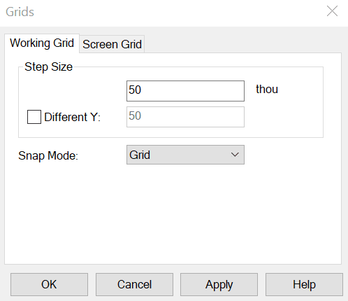
The default technology file uses a 50 thou grid.
Some standard symbols from PPL are shown below with their respected length and width. The styles used in creating the component schematic symbol are (viewable in the design technology):
Line style 'pin' which has a width of 6.
Line style 'thin' which has a width of 10.
Text style 'default' which has a width of 50 and a line width of 5 using the "System Stroke Font".
Using these details as a guide you will be able to create consistent schematic symbols.