What does it take to build a Line Follower Car? Part 3
Follow article Dave from DesignSpark
How do you feel about this article? Help us to provide better content for you.
Dave from DesignSpark
Thank you! Your feedback has been received.
Dave from DesignSpark
There was a problem submitting your feedback, please try again later.
Dave from DesignSpark
What do you think of this article?
I am currently having my internship with RS Components. One of my main functions is to work on a project that is related to the Renesas Micom Car Rally.
The aim is to simplify and improve on the procedure of assembling, programming and customising a cover for the Micom car kit. In the process provide related materials to the concepts for building a line following car that is easy to understand.
Overview
In this article, I will be focusing on, the creation of the Micom car cover using DesignSpark Mechanical. If you have not seen my previous articles, about the introduction to the Micom car kit or the programming and the creation of the car plates, you can find part 1 here and part 2 here.
Creating the car cover
The purpose of creating the cover for the Micom car is to protect the circuit boards, as well as to prevent any accidental human contact with the circuits which might be unsafe. Another benefit of the cover is that it may be able to increase the car's performance when the cover is aerodynamically designed.
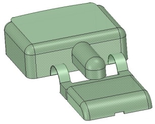
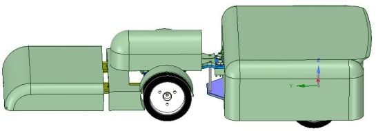
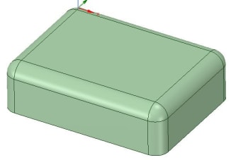
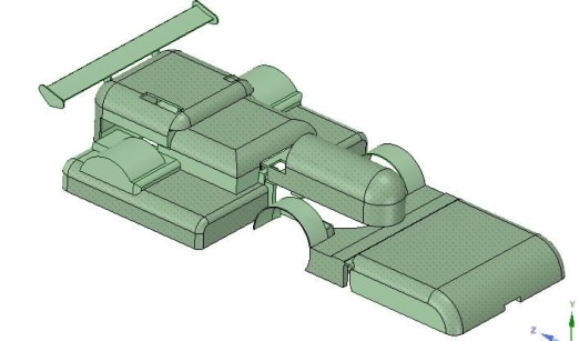
By using DesignSpark Mechanical, It was easy to create the simple car cover shown in the picture to the left. The various 3D models of the car covers can be downloaded at the end of this article. The 3D models of the car below illustrates the fully assembled Micom car, which consist of the various car covers.

If you would like to create your own or custom car cover, you can follow the next few simple steps, which illustrates how I created one section of the car cover. You can use these steps to create a model for your reference, practice or use the final design.
I will be showing how to create the main body cover which is the largest and most complex section, consisting of a mini spoiler. With this knowledge, creating most of the remaining covers will be a piece of cake.
While designing the car cover, it is a good practice to follow the rules of aerodynamics. The following points are the basic rules of aerodynamics that you should follow to increase the performance of the car.
- Rounding up of front facing edges - decreases pressure on the front (improves streamline of the car's front)
- Avoid protruding edges on the side of the body and the roof - reduces roof and side wall drag (improves streamline of the car's sides and roof)
- Adding of rear spoiler - increase pressure and decrease drag at the rear of the car (improves streamline of the car's rear and reduces lift)
The dimensions of the main body cover is shown in the picture below, followed by a tutorial video and the steps to create it.
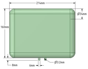
Note: The picture showing the dimensions of the main body cover is taken from a top view which has a height of 63.5mm.
STEP: 1 Download and installation (skip this step if you already have DesignSpark Mechanical installed)
- Download DesignSpark Mechanical HERE
- Install and Run the application
STEP: 2 Creating a new sketch design
- Click on File >> New >> Design
- Click on View Plane on the top toolbar located in the “Orient” section
- Then, press "R" and click anywhere on the plane to create the start the rectangle
- Next, enter value of 214mm and 160mm

Note: Once the dimensions have been keyed in, the sketch should look roughly like this picture on the left.
Step: 3 Creating the 3D model
- Press "H" to display the design in a trimetric view
- Then, press "P" and click on the surface of the rectangle
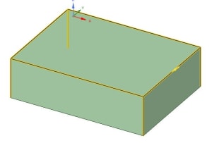
- Once the surface is selected, drag and hold the surface downwards for 63.5mm or just key in the height after pulling

Note: Once the rectangle is pulled, the sketch should look roughly like this picture on the left.
Step: 4 Rounding the edges
- While on the pull tool, double click on the outline of the top rectangle
- Hold the ctrl key and select the corner adjacent lines shown in the picture below
- Once the outline of the rectangle and its corner adjacent lines are highlighted, press on the spacebar and key in a value of 17mm
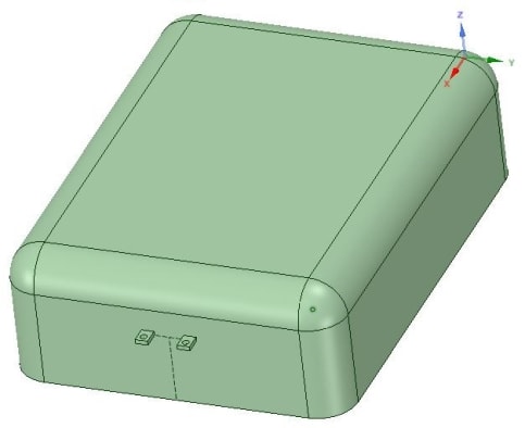
Note: Once the corners have been rounded, the 3D model should look roughly like the picture on the left
Step: 5 Creating a shell
- Click on the shell tool
- Then, click on the bottom surface of the 3D model

Note: The shell tool can be found in the insert toolbar at the top

Note: Use the scroll button to rotate the model. After shelling the model, it should look roughly like the picture on the left
Step: 6 Adding supporting model
- Click on the Construction Line then, click on the front facing rectangle surface
- Then, press "V" for a Plan View orientation of the model
- Click on the middle of the bottom line to mark the start of the construction line (to locate the mid-point, mouse over the middle of the line where a triangle will appear which indicates the mid-point of the line)
- Draw 2 lines of 33.5mm and 14mm where, the mid-point of the 14mm line meets the end of the 33.5mm line. The picture below shows the position where the lines should be drawn

- Press "R" and click on either end of the 14mm line
- Create a 6mm X 2mm rectangle above the line
- Then press "P" and pull the newly created surface 8mm outwards
- Draw a circle of diameter 3.2mm, with middle 3mm from the middle of the outside edge of the new model
- Then pull it through the model to make a hole
- Create the same model for the other end of the 14mm line
- Right click on "Curves" and delete it as shown in the picture below

Note: The unwanted construction lines can be found in the structure tree located on the left drop down bar.
Step: 7 Adding the spoiler
- Click on the back line of the top facing rectangle then, pull it outwards for 15mm
- Select the 3 point arc tool, then select the new surface
- Click on the ends of the new surface and create a 30° arc using the tool
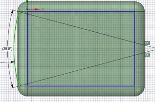
Note: When creating the arc, make sure that the correct surface is selected. After creating the arc, the model should look roughly like the picture on the left
- Then, pull the surface of the arc and the rectangle surface downwards for 3mm (make sure that the add option of pull is selected)
- Select the back line of the top facing surface of the spoiler and pull inwards for 5mm (make sure that chamfer is selected as the pull option)
- Click on both the edges of the spoiler and pull to round the edge for 5mm (make sure that round is selected as the pull option)

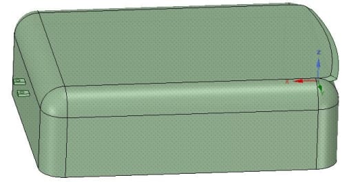
Note: When pulling, make sure that the right option is selected. After rounding the edges the model should look roughly like the picture on the left
Finally the main body cover of the car is now completed and should look roughly like the model in the picture below.
You can now continue with creating the other sections of the car cover or, if you are feeling ambitious, you can try to create your own custom car cover that might be much cooler.
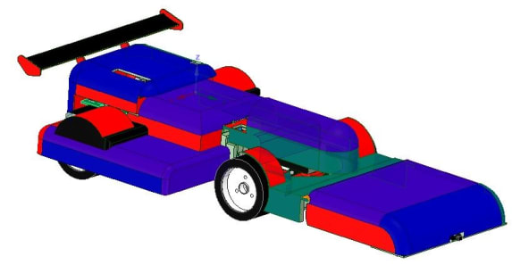
By applying the aerodynamics rule to my own cover design, I have created my own custom car cover which is shown in the pictures below.
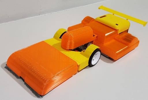
After printing out the cover using a 3D printer and fitting it on the Micom car, the final product of the car cover can be seen in the picture below. You can also print the car cover using different filament for the 3D printer, to print out different colours that you prefer (there are filaments which can glow in the dark!). The 3D printer filament can be found here.
If you find that my cover design for the car is awesome, and would like to use it on your Micom car, you may download the model files that can be found at the end of the article for printing or for your reference.
Testing Driving the Car
After fitting the 3D printed cover onto the car, the performance of the car was put to the test. The video below shows the car manoeuvring through the basic course.
After comparing the timing of the car with and without the cover, it was discovered that the car fitted with the cover was slower by about 1-2 seconds. This is due to the extra weight that is added to the car, which decreases the speed of the car slightly. As the speed of the car is not as fast as those in the F1 race, the aerodynamics design of the cover does not have that much of an effect on the car. But, with the car cover, the car looks much better/cooler as the wires and circuit boards are not exposed, thus it is also much safer.