WAKING YOURSELF UP – design your own alarm-clock from scratch
Follow article Dave from DesignSpark
How do you feel about this article? Help us to provide better content for you.
Dave from DesignSpark
Thank you! Your feedback has been received.
Dave from DesignSpark
There was a problem submitting your feedback, please try again later.
Dave from DesignSpark
What do you think of this article?
Are you tired of waking up with an appalling racket? Do you have to deal with complex sets of instructions each time you want to change the hour?
My alarm-clock made my ears ring each morning, and I woke up with a murderous look, so I decided to program and design my own alarm-clock with a simple configuration and my own melodies, as well as some add-ons like temperature reading.
This project basically consists of an alarm-clock with a LCD display 2x16 based on the module RTC (real time clock) DS3231 and programmed with PIC16F877A. Its operation is plain sailing, as it is only based on 2 push-buttons, PB1 and PB2. PB1 holds the “MODE” and “SELECT” functions while PB2 is the “ADJUST” button.
The alarm can be programmed to ring at a certain hour of the day and there are 3 different songs to choose from (you can use whatever songs you like instead). The alarm system also enables SNOOZE mode operation, which allows the user to sleep 5 more minutes until the alarm rings again (this option will be limited to 2 consecutive times at 5 and 10 minutes after the programmed hour).
PCB Design and components
The PCB has been designed with DesignSpark PCB 8.0 and the schematic and PCB files are attached at the end of this article. It is a 2 Layer Board with copper pour areas on both sides (5 V on top side and Ground on bottom side). Its area is 82.5 x 65 mm.
The components used in this project are:
- 8.4 V Battery
9 V transformer with connector
- Switching regulator with 5 V output
- Microcontroller PIC16F877A
- 4 MHz Oscillator (for the μC)
- Real Time Clock (RTC) IC DS3231
- LCD display 2x16
- 2 Push-Buttons
- Buzzer (requires a NPN transistor)
- Resistors with various values
- Capacitors with various values and functions (bulk capacitors, decoupling capacitors)
- Several Pin Headers and cables
Source code and operation
The source code is attached at the end of this article. It has been written in C using MPLAB® IDE v8.89 and HI-TECH ANSI C Compiler. The current code uses 71.7% of PIC16F877A’s program memory and 32.1% of its data space.
Before designing the PCB, the code has been verified using PICDEM 2 PLUS Demo Board with the debugger MPLAB® ICD 3.
The alarm-clock’s operation is explained below. It is far easier that it may seem at first sight.
1. How to Set Normal Time
TIME SET mode allows the user to set Normal Time. In order to change from LOCK mode to TIME SET mode, PB1 must be pressed less than 0.8 s. Then, the letters ‘TS’ appear written on the upper left corner of the LCD display.
While in TIME SET mode, pressing PB1 will change the selected parameter whereas pressing PB2 will allow the user to adjust it (holding PB2 will adjust the parameter more quickly). When the configuration is completed, the user can return to LOCK mode by holding PB1 until the letters ‘TS’ disappear (around 0.8 s).
In TIME SET mode the following parameters can be adjusted:
- Hour and minutes
- Hour format 12/24h. Alarm Time’s hour will have the same format selected for the Normal Time’s hour.
- Year (2000-2099), only last 2 digits shown.
- Month and date. Date will reset to 1st if date, month and year are inconsistent (e.g. 31st April or 29th February of no leap year)
- Date format: European (DD/MM/YY) or American (MM/DD/YY)
- Temperature: ºC (European format) or ºF (American format)
- Day of the week adjusts automatically when year, month or date is changed. In European format Spanish letters for the day of the week are shown (‘L’, ‘M’, ‘X’, ‘J’, ‘V’, ‘S’, ‘D’) while in American format English-speaking letters are displayed instead (‘Mon’, ‘Tue’, ‘Wed’, ‘Thu’, ‘Fri’, ‘Sat’, ‘Sun’).
2. How to Set Alarm Time
ALARM SET mode allows the user to set Alarm Time. In order to change from LOCK mode to ALARM SET mode, PB1 must be pressed at least 0.8 s. Then, the letters ‘AS’ appear written on the upper left corner of the LCD display.
While in ALARM SET mode, pressing PB1 will change the selected parameter whereas pressing PB2 will allow the user to adjust it (holding PB2 will adjust the parameter more quickly). When the configuration is completed, the user can return to LOCK mode by holding PB1 until the letters ‘AS’ disappear (around 0.8 s).
In ALARM SET mode the following parameters can be adjusted:
- Alarm hour and minutes
- Alarm mode: OFF (no picture), ON (a bell is shown on the upper right corner of the LCD display), SNOOZE (a bell and a snooze symbol are shown). These symbols will persist when the user returns to LOCK mode and they will even appear in TIME SET mode.
- Alarm Song (‘Canción’ in Spanish): one of the following 3 songs related to waking up can be chosen: 1:”Levántate pamplonica”; 2: “Las mañanitas”; 3: “Quinto levanta”. If you don’t like them, you can always change them.
3. How to Switch the Alarm Off
When the alarm is ringing, it can be silenced by pressing either button. However, there are some differences depending on which alarm mode was chosen.
- Alarm mode ON: pressing either button (it doesn’t matter how long) switches the alarm off. A beep immediately afterwards will confirm the alarm has been switched off. The alarm won’t ring until next day at the same hour.
If no push-button is pressed, the chosen song will be played 3 times and then the beep will signal the ending. The purpose of this restriction is to avoid disturbing the neighbours if the user wakes up earlier and doesn’t remember to disconnect the alarm.
- Alarm mode SNOOZE: the alarm will ring at the programmed hour and 5 and 10 minutes later, unless the user switches it off. Each time the chosen song will be played at most 3 times.
When the alarm is ringing, pressing either button will silence the alarm, but it won’t switch it off (unless it is the third time the alarm is ringing). In order to completely disconnect the alarm PB1 or PB2 must be held for 5 seconds.
It is supposed the user has to be fully awake to hold one pushbutton for 5 seconds. It doesn’t matter if the user starts holding the button when the alarm is ringing or during the 5 minutes between each time the alarm rings.
When the alarm is disconnected (because it was the third time or because the user has held one push-button for 5 s) a beep will indicate the alarm has been switched off. The alarm won’t ring until next day at the same hour.
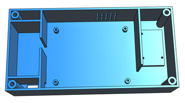
3D Design
The 3D design has been done with DesignSpark Mechanical 2.0 and the 3D files are attached at the end of this article. The design has 3 major parts: box, cover and push-buttons.
> Box design
The box counts with the following compartments:
- Left compartment: it can contain the battery used to feed the PCB. However, a small 9 V transformer can be used instead. The transformer is fitted in a hole next to the battery’s compartment. Another hole allows the cables that come from the transformer to reach the PCB.
- Central compartment: it hosts the PCB. The PCB possesses 4 holes (one on each corner) in order to join the PCB to the four small columns the central compartment has. M2 or smaller screws should be used. The central compartment also has several holes in the wall next to the buzzer to improve the sound.
- Right compartment: it has a platform with 3 small holes to anchor the integrated circuit DS3231, real time clock used in the project.
> Cover design
The cover has one rectangular hole to fit the LED display and 2 circular holes for the push-buttons. The cover and the box can be joined using M4 screws.
Depending on the exact 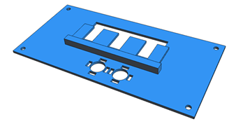
> Push-Button design
Specifi
When the push-button (3D piece) isn’t pressed the screw’s head mustn’t touch the push-button (through-hole component) located on the PCB. When the push-button is pressed the thread has to slide through the push-button box’s hole and the head has to touch the push-button (through-hole component) located on the PCB. When the pressure disappears the spring must have enough strength to pull the screw back.
Several springs and screws (attention to their length has to be paid too) may be required until finding the proper components.
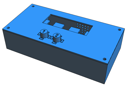
> Assembly
It is highly recommended to view the assembly model. The visualization of each of the pieces that are part of the assembly can be activated or deactivated separately (this option can be very useful).
Video
(*) Attached files
- Source code (attachments 1-5): project code (1), LCD library header (2), LCD library code (3), I2C library header (4) and I2C library code (5). (1), (3) and (5) must be included as Source Files in a MPLAB® Project. PIC16F877A must be the selected device. In other case, configuration settings will have to be changed.
IMPORTANT NOTICE: it isn’t compulsory to include (2) and (4) as Header Files in the created MPLAB® Project (although it is highly recommended). However, headers (2) and (4) must be in the same file as (1), (3) and (5); or the compiler will fail in building the project.
- PCB files (attachments 6-8): schematic (6), PCB design (7) and 3D package library (8). (6) and (7) should be included in a DesignSpark PCB Project. (8) should be enabled using the Library Manager to visualize the PCB’s 3D View as it was intended.
- 3D design files (attachments 9-16): box (9), cover (10), LCD support 1 (11), LCD support 2 (12), push-button 1 (13), push-button 2 (14), push-button box (15) and 3D assembly model (16). Files (11), (12) and (15), with number in bold, must be used 2 times.