Debug Arduino LCD Keypad Shield with Digital Discovery
Follow article Dave from DesignSpark
How do you feel about this article? Help us to provide better content for you.
Dave from DesignSpark
Thank you! Your feedback has been received.
Dave from DesignSpark
There was a problem submitting your feedback, please try again later.
Dave from DesignSpark
What do you think of this article?
In this project, you will learn how to debug an HD44780 display.
You will need a Digilent Digital Discovery (136-8070) , a combined logic analyzer and pattern generator instrument. The Digital Discovery allows you to debug, visualize, and simulate digital signals for most embedded projects. We use Python to debug the LCD display.

Let's go through all steps.
Step 1: Connect LCD Display to Arduino Uno
To get started, we connect LCD display to Arduino Uno (769-7409) based on the following wiring table. The provided Arduino sketch sets up the LCD's number of columns and rows, initializes the serial communications, and enables the backlight. The LiquidCrystal library is used.
| LCD Pin | Arduino Uno Pin |
|---|---|
| RS | 8 |
| Enable | 9 |
| D4 | 4 |
| D5 | 5 |
| D6 | 6 |
| D7 | 7 |
| Backlight control | 10 |
| R/W | Ground |
Step 2: Connect the hardware to Digital Discovery
After we connect the LCD shied to the Arduino Uno, we need to connect the whole system to the Digital Discovery based on the following wiring map.
| Digital Discovery Pin | LCD Shield Pin |
|---|---|
| GND | GND |
| DIN0 | EN |
| DIN1 | RS |
| DIN2 | D4 |
| DIN3 | D5 |
| DIN4 | D6 |
| DIN5 | D7 |
Note: Ground should be connected before any other connections are made.
Step 3: Write Python Script to debug the LCD Shield
Real-time data acquisition and analysis are used. The script uses the following four threads:
- The main thread (GUI) initializes equipment and is responsible for the GUI operation.
- The acquisition thread collects real-time data from Digital Discovery and puts data into a queue.
- The raw data processing thread. Reads data from the queue. Latching only at rising edges of EN and putting data into another queue.
- The data processing thread. Reads latched data from the second queue and simulate the behavior of the HD44780 display.
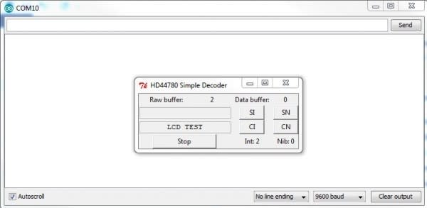
Step 4: Debug the LCD Shield
Run the Python script. If the Raw buffer or Data buffer are filling very quickly, the sample rate should be reduced. The “Int” indicator shows if the initialization was detected by the script. A value of “2” means that initialization was completed successfully and values of “0” or “1” indicate an incomplete process.
Data sent to the LDC shield can be seen in Digilent WaveForms Logic Analyzer instrument. In the Logic Analyzer, add a bus with clock on rising edge of the EN signal. Next, add the RS signal as a separate signal and set trigger mode to normal with triggering on a rising edge of the EN signal.
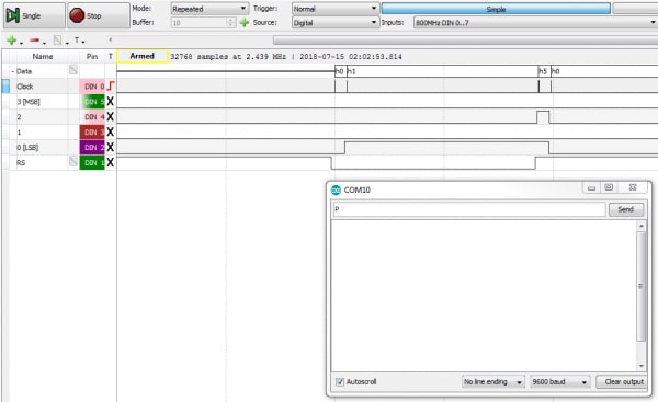
The project details, the Arduino sketch, Python scripts are available at Digilent Documentation Page.