TOP 20 Basic Electronic Circuits with Analyses Diagrams
Follow article
 Dave from DesignSpark
How do you feel about this article? Help us to provide better content for you.
Dave from DesignSpark
Thank you! Your feedback has been received.
Dave from DesignSpark
There was a problem submitting your feedback, please try again later.
Dave from DesignSpark
What do you think of this article?
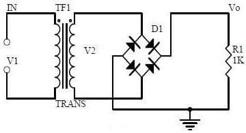
1. Bridge Rectifier Circuit
Design Points:
1) Know well the unidirectional conductivity of the diode.
The PN junction of the diode is in the on-state when the forward voltage is applied, and in the off state when the reverse voltage is applied.
2) Volt-ampere characteristic curve.
3) Set up the ideal switch model and constant voltage-drop model
The ideal model means that when the diode is forward-biased, its voltage drop is 0, and when it is reverse-biased, its resistance is considered to be infinite and the current is zero.
The constant voltage drop model means that when the diode is turned on, its voltage drop is a constant value: 0.7V for silicon and 0.5V for germanium.
4) Observe the process of bridge rectification current flow
When u2 is the positive half-cycle, the diodes Vd1 and Vd2 are turned on, while the diodes Vd3 and Vd4 are off, the current of the load RL flows from top to bottom, and the load gets the same voltage as the positive half-cycle of u2. In the negative half cycle of u2, the actual polarity of u2 is up positive and down negative, at this time, Vd3 and Vd4 are turned on and Vd1 and Vd2 are turned off. The current on the load RL still flows from top to bottom, getting the same voltage for the positive half cycle u2.
5) Calculate the diode reverse voltage Vo, Io.
Uo=0.9U2, Io=0.9U 2/RL, URM=√2U2
Note: Get words detail from Bridge Rectifier Circuit Basic Parts
2. Power Filter Circuit

Design Points:
1) Have the process analysis of power supply filtering.
Power supply filtering is to connect a larger capacity capacitor in parallel at both ends of the load RL. Since the voltage at both ends of the capacitor cannot change suddenly, so as to the ends of the load. The output voltage can be smoothed and the purpose of filtering can be achieved.
2) Know the waveform formation process.
When the output terminal is connected to the load RL, the load and the capacitor C get current from the power supply. Due to the energy storage effect of the capacitor C, the voltage fluctuation on RL is greatly reduced. Capacitor filtering is suitable for occasions where the current does not change much. The LC filter circuit is suitable for occasions where the current is large and the voltage ripple is small.
3) Calculation
Selection of filter capacitor capacity and withstand voltage
The output voltage Uo of the capacitor filter rectifier circuit is between √2U 2~0.9U2, and the average value of the output voltage depends on the discharge time constant.
Capacitance capacity RLC≥(3~5)T/2, where T is the cycle of AC power supply voltage. In practice, it is often further approximated as Uo≈1.2 U2, the maximum reverse peak voltage of the rectifier tube URM=√2U2, and the average current of each diode is half of the load current.
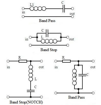
3. Signal Filter
Design Points:
1) Find out the role of the circuit.
Attenuate unwanted signal components in the input signal to a sufficiently small extent, but at the same time, the useful signal must be passed smoothly.
a. List Differences and similarities with filters:
The signal filter is used to filter the signal, and its passband is a certain frequency range, while the power filter is used to filter out the AC component, allowing the DC to pass, so as to keep the output voltage stable. The AC power supply is only allowed a certain frequency is passed.
The same point: all work with the amplitude-frequency characteristics of the circuit.
2) Have the impedance calculation of LC circuits
When in series connection, the circuit impedance is Z=R+j(XL-XC)=R+j(ωL-1/ωC).
When in parallel connection, the circuit impedance is Z=1/jωC(R+jωL)÷(1/jωC+R+jωL).
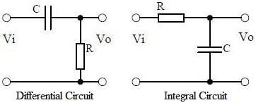
4. Differential and Integral Circuit
Design Points:
1) Know well the function of the circuit, similarities and differences compared with the filter.
2) Analyze the voltage change process of the differential and integral circuit according to the voltage change waveform diagram.
3) Calculation includes time constant, voltage change equation, selection of resistance and capacitance parameters.
5. Common-emitter Amplifier Circuit

Design Points:
1) It is necessary to consider the transistor structure, the current relationship between the pole, the characteristic curve, and the amplification conditions.
2) Figure out the role of the components, the purpose of the circuit, the voltage amplification factor, the phase relationship of the input and output signal voltage, and the equivalent circuit diagram of AC and DC.
3) Calculation consist of static operating point, and voltage magnification.
6. Biased Common-emitter Amplifier Circuit (voltage divider)

Design Points:
1) Find out the function of the components, the purpose of the circuit, the voltage amplification factor, the phase relationship of the input and output signal voltage, and the equivalent circuit diagram of AC and DC.
2) Analysis of the negative feedback process of current series, and the influence of negative feedback on circuit parameters.
3) Calculate the static operating point and voltage magnification.
4) With the help of controlled source equivalent analysis.
7. Common-collector Amplifier Circuit (emitter follower)

Design Points:
1) Figure out the function of the components, the purpose of the circuit, the voltage amplification factor, the phase relationship of the input and output signal voltage, the equivalent circuit diagram of AC and DC, and the input and output impedance characteristics of the circuit.
2) Analysis of the negative feedback process of current series, and the influence of negative feedback on circuit parameters.
3) Calculate the static operating point and voltage magnification.
8. Circuit Feedback Block Diagram

Design Points:
1) Learn the concept of feedback, positive and negative feedback and their judgment method, parallel feedback and series feedback, current feedback and voltage feedback.
2) Calculate the amplification gain with negative feedback circuit.
3) Figure out how negative feedback affects the circuit's amplification gain, pass band, gain stability, distortion, input and output resistance.
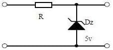
9. Diode Voltage Regulator Circuit
Design Points:
1) Use PN junction reverse breakdown state.
2) Choose the reference voltage source, and load current.
3) Calculate voltage stabilization value.
10. Series Regulated Power Supply

Design Points:
1) Acquire the circuit function: voltage transformation, rectification, filtering.
2) Get the adjustment parts, reference voltage, comparison amplifier and sampling circuit.
3) It is necessary to make a circuit load to obtain a stable voltage.
11. Differential Amplifier Circuit

Design Points:
1) According to the role of the components of the circuit, the purpose of the circuit, and the characteristics of the circuit.
2) Analysis of the working principle of the circuit: how to amplify differential mode signals and suppress common-mode signals.
3) Use the circuit's single-ended input and double-ended input, single-ended output and double-ended output working mode.
12. FET Amplifier Circuit
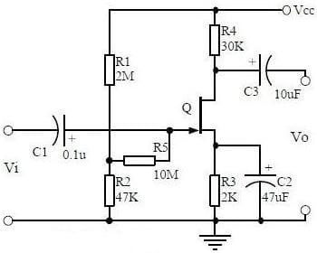
Design Points:
1) Find out the classification, characteristics, structure, transfer characteristics and output characteristic curves of FETs.
2) Acquire the characteristics of the field-effect amplifier circuit.
3) Analyze the Applications of the field-effect amplifier circuit.
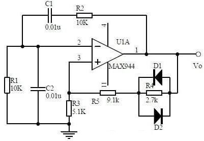
13. Frequency Selection (band pass) Amplifier Circuit

Design Points:
1) Figure out the role of each component, the characteristics of the frequency-selective amplifier circuit, and the role of the circuit.
2) Have the calculation of characteristic frequency and selection of frequency-selective component parameters.
3) Draw the Amplitude-frequency characteristic curve.
14. Operational Amplifier Circuit
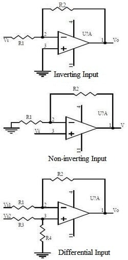
Design Points:
1) Learn the concept of an ideal operational amplifier, the input terminal of the operational amplifier is virtual short-circuit, and the input terminal of the operational amplifier is virtual open.
2) Figure out the main purpose of the op-amp circuit of the inverting input mode, and the phase relationship between the input voltage and the output voltage signal.
3) Set up the expressions of gain, input impedance, and output impedance in non-inverting input mode.
15. Differential Input Operational Amplifier Circuit

Design Points:
1) Find out the features and purpose of the circuit.
2) Figure out the relationship between output signal voltage and input signal voltage.
16. Voltage Comparator Circuit
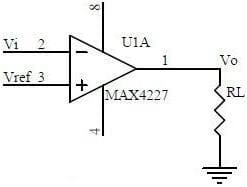
Design Points:
1) Find out the role of the voltage comparator, and its working process.
2) Draw the input-output characteristic curve of the comparator
3) Make it into a hysteresis comparator.
Note: Get more info from Comparator in Electronic Circuits
17. RC Oscillator Circuit
Design Points:
1) Understand the composition of the oscillating circuit, the role of the circuit, the phase conditions for vibration, and the conditions for the vibration and balance amplitude of the oscillating circuit.
2) Draw the relationship curve between RC circuit impedance and frequency, and the relationship curve between phase and frequency.
3) Have the phase condition analysis of RC oscillator circuit, oscillation frequency calculation, and take components selection.
18. LC Oscillator Circuit

Design Points:
1) Have analysis of oscillation phase conditions.
2) Draw DC equivalent circuit diagram and AC equivalent circuit diagram.
3) Have the calculation of oscillation frequency.
19. Quartz Crystal Oscillator Circuit

Design Points:
1) Know the characteristics of quartz crystal, the equivalent circuit of quartz crystal, the characteristic curve of quartz crystal.
2) Give priority to features of quartz crystal vibrator.
3) Calculate the oscillation frequency of the quartz crystal vibrator.
20. Power Amplifier Circuit
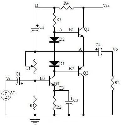
Design Points:
1) Analyze the working process and crossover distortion of Class B power amplifier.
2) Employ the compound rule of compound triode.
3) Know well the working principle of the class A and B power amplifier, the bootstrap process, and the characteristics of the class A and B power amplifiers.