Thin film backlighting technology for user interfaces and illuminated panels.
Follow article
 Dave from DesignSpark
How do you feel about this article? Help us to provide better content for you.
Dave from DesignSpark
Thank you! Your feedback has been received.
Dave from DesignSpark
There was a problem submitting your feedback, please try again later.
Dave from DesignSpark
What do you think of this article?
Stadium IGT's patented thin film backlighting technology uses specialised printing processes for the accomplishment of light extraction from the light-guide surface using side emitting LED's embedded within the light-guide structure.

Transparent materials guide light by means of Fresnel’s Law of Refraction, and in particular the phenomenon of Total Internal Reflection, as illustrated in Figure 1. In addition to fibre optic communications, this physical phenomenon is the basis for backlighting for LCD screens in mobile phones and laptops. These applications require a thin light source directly behind the liquid crystal panel to illuminate the screen. The light sources (LED’s or CCFL lamps) are located at the edge of the display. Light is coupled into a thin polymer plate, trapped by total internal reflection. Surface features on the plate extract light by reflection and refraction, with feature density varying with the distance from the light source(s) to achieve a uniform distribution of light to the display. The conventional technology for the light-guide is an injection moulded plate. Sophisticated optical modelling software tools are used to achieve a high performing design (uniformity is typically the key parameter, but energy efficiency is also considered). This design is then transferred to a hard tooled metal master for an injection moulding process. The resulting moulded parts are then mechanically assembled with light sources, reflector and diffuser, to obtain a rectangular and uniform, panel of light.
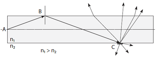
Figure 1: A light source at position A, exhibiting Total Internal Reflection at position B for is a material of refractive index n₂, where n₁ is greater than the refractive index of the surrounding medium n₂. At position C the light is scattered by a light extraction feature, and exits the light-guide.
This light-guide approach is a radical departure from moulded light-guides and demonstrates significant cost and performance benefits, as summarised in Table 1. The LED’s can be located anywhere across the light-guide substrate, with integrated optical barriers isolating independent light-guides, and these light-guides placed at custom locations as determined by the application design.
| Advantages: |
| Thin construction |
| Uniform illumination |
| Low power |
| Low setup costs |
| Mechanically flexible |
| Segmented illumination |
| Illumination effects: |
| Dynamic colour change |
| Dynamic colour fade |
| Secret until lit graphics |
Table 1: Summary of technology advantages and potential illumination effects.
Design LED working with Stadium IGT have pioneered the use of optically transparent acrylic as light-guides. This patented approach offers the potential to integrate multiple light-guides on a single substrate. In this approach an opaque polymer layer is used to form a cavity into which the individually printed and laser cut acrylic optics are dispensed. This optically opaque cavity material serves to isolate adjacent light-guides preventing any light bleed.
In the simplest light guide technology platforms the transparent sheet is used as the light guide structure, and in more complex constructions it’s used as a transparent substrate on which additional material are placed to form layered light guide of independently illuminated regions.
To achieve this structure with moulded light-guide techniques would require the manufacture of multiple moulded components, potentially from multiple mould tools, and a second process to integrate them to an additional structure, potentially a moulded panel, to provide the mechanical placement and optical isolation.
Capacitive Sensing Technology Platform
Capacitive sensing describes a number of non-mechanical electric field methods of achieving a switch technology. Typically, an electric field is projected above a surface where a finger interferes with the field and this is measured by an electronic circuit, registering activation. One of the major issues with capacitive switch technology is achieving switch graphic illumination without interfering with the electric fields.
In this approach the light-guide delivers the light across and onto the capacitive switch electrodes. Stadium IGT / Design LED’s technology platforms either embeds LED’s populated on a circuit substrate into the light-guide, or optically couple the LED to the edge of a transparent sheet.
An LED embedded in the light-guide, with the capacitive switch electrode layer in LED interconnect layer within the light-guide structure. This novel approach, termed the “Active” technology platform, shown schematically in Figure 2, is the most optically efficient system, removing optical losses which occur with a separate light-guide placed at LED windows and optical / mechanical alignment issues. For a given luminance specification, the increase in optical efficiency results in a reduction in the required number of LED components, and a potential reduction in total system costs.
Figure 2: Schematic illumination of an Active light-guide construction with the LED’s embedded within the optical acrylic light-guide, bound by the light fast cavity.

A simpler, “Passive” approach, places the LED, the LED circuit and the capacitive switch electrode on separate printed circuit and the light-guide structure is laminated to this substrate. Although significantly less optically efficient that the above “Active” construction, this may be suited to lower luminance and cost sensitive applications, with no requirement for independently illuminated segments.
The requirement for the optical isolation of adjacent icons and the properties of conductive electrode materials generally leads to the implementation of a combination of the “Active” and “Passive” platforms. In this approach, illustrated in Figure 3, the optically isolated light-guides are produced on a transparent substrate but with no LED’s or conductive print on the substrate. Instead the LED’s are placed on a second substrate, together with the capacitive switch electrodes. Apertures are cut in the light-guide assembly at the LED locations, through the optical supporting substrate. On the lamination of the light-guide structure to the PCB the LED’s are coupled into the light-guide segments.
The resulting structure is an integrated light guide assembly, optimised for optical performance, addressing Design for Manufacture (DFM) principles in both its manufacture and installation in the application. The printing processes result in lower design, tooling and prototyping time and costs, and overall lower unit cost.
Figure 3:
a) The light extraction graduation print is applied to the substrate, with gradient indicated by the arrow.
b) Shows the position of the LED aperture within the acrylic light tile.
c) The assembly is bonded to the circuit to which the LED’s and capacitive sensor pads are mounted.

A light-guide thickness of <1.2mm is a significant reduction in comparison the traditional approach of top emitting LED’s through a transparent electrode. The total thickness of the light-guide assembly is driven by available LED package and can be as low as 0.4mm. Established products are based on 0.6mm thick side emitting single colour LED’s, and 1.2mm thick RGB packages.
From a manufacturing perspective, this approach is an extension of the materials and processes used in the manufacture of flexible printed circuits. Consequently, Design LED Products licensing of this technology to Stadium IGT with proven design, development and manufacturing track record in this industry has ensured the manufacture of an integrated assembly. This is of particular significance given the requirements of component and graphic registration and their impact on the perceived optical quality of the finished product.
Design Recommendations
The variables which influence a given design extend further than the colour of the illumination. The LED manufacturer, part number and resulting specification directly influence the optical and electrical performance. In addition the number of independently illuminated areas, the required pitch between icons, the number of colours, and the mechanical formability directly influence the design process. Consequently it is difficult to provide a comprehensive set of design rules. Instead, what follows is a set of recommendations which form the basis for an implementable design.
The simplest format is illuminated icons / switches with a single colour and no colour change for any element. In this case all icons are illuminated by a single light guide with LED’s positioned at locations appropriate to the graphic design and the mechanics of the application.
As the number of independently illuminated areas increases, the physical dimensions of the light-guide and the separation between adjacent light-guides form constraints to the design. Typically, the minimum separation between adjacent icons is 6mm, as shown in Figure 4, with a 4mm opaque barrier between the light-guides.

Figure 4: Example construction for 2 icons, with the optically opaque cavity supporting a 6mm separation. Dimensionally a minimum overlap of 0.25mm is recommended between the illuminated icon position, the light extraction print and the inner surface of the cavity.
A reduced icon pitch is possible in some designs, with suitable icon shapes, luminance expectations, and the applications’ operating modes. However achieving optical isolation with a reduced icon pitch may require significant revision to the platforms discussed above and further material processing. These considerations may impact development and processing costs and should be considered with respect to the perceived benefits.
In considering the requirement for multiple single colours or dynamic colour change on an application, the balancing of the optical performance requires consideration. In addition to the LED luminous intensity varying with manufacturer, with part number, and therefore component cost, the LED “brightness” also varies with the emitted colour.
Relative luminous intensities are shown in Table 2 for components available from mainstream LED manufacturers. If, for example, an icon is to be switched between red and green illumination, then it is common practice to increase the number of green LED’s to compensate for the reduced luminous intensity.
| Emitted colour: | Relative Luminance: |
| White | 100% |
| Red | 50% |
| Green | 20% |
| Blue | 10% |
Table 2: Relative luminance figures for commercial side-emitting LED’s relative to the luminance from white light emitters.
A requirement for dynamically cycling multiple colours may be resolved using RGB LED packages. These devices have red, green and blue emitting die in a single package, but with notable compromises in design flexibility. The RGB components are typically 1.2mm thick, double the thickness of commonly used single colour components. The additional thickness increases the thickness of the light-guide which limits the mechanical flexibility of the light-guide assembly and influences the light extraction gradient. The use of 3 die requires 6 contacts, and therefore a factor of 3 increase in electrical tracking. The increased cost of RGB packages may mean that the LED’s are the primary contributor to the total BOM cost.
Where there is a “static” colour requirement, an alternative to coloured light emitter is the use of white LEDs and a coloured filter. The filter, either as an optical film laminated into the assembly or a translucent print applied to the graphic material, determines the perceived colour. Provided that the optical properties of the filter are matched to the spectral density from the LED’s, there is the potential for a white LED and filter construction to provide a higher luminance than an equivalent coloured LED.
The aesthetics of the graphic can be enhanced by the use of a “dead front” or “secret until lit” print. This print is applied to the graphic overlay beneath the upper print. The properties of this print are adjusted to balance the lit and unlit conditions for the LED(s) which illuminate the icon. In the off-state, the print should absorb ambient light shining onto the graphic, and hide the light-guide structure. When the LED(s) are powered, the optical absorption must not reduce the light extracted from the light-guide below the luminance level required by the application.
The adjustment of the dead front print properties is assisted where the surface print is as dark as possible, hiding the tint on the dead front print in the areas of the icon.
Materials Selection
In addition to balancing the optical requirements of colour luminance, and dead front, the platforms developed support a number of materials, both commonly available standard materials, and unique compositions.
| Substrate Material | Polyester, Polyimide, FR4 |
| Overlay Material | Polyester, Polycarbonate |
| Light guide Thichness | 0.5-1.2mm (LED dependent) |
| Assembly Thickness | 1-2mm (typical) |
| LED Packages | Low profile side emitting SMT |
| Typical Forward Current | 20mA |
| Typical Forward Voltage | ~ 3V |
Table 3: Supported materials for light-guide assemblies.
The passive platform of a printed flexible sheet is laminated over a LED circuit and capacitive sensor pad. The light-guide can be laminated to a rigid FR4 substrate. Alternatively the light-guide can be laminated to a circuit on a polyester or Kapton based circuit when a degree of mechanical flexibility is required.
Similarly, the construction outlined in Figure 3 with an LED aperture cut in optical acrylic produces an assembly which can be laminated to polyester, Kapton or FR4.
Microcontroller Integration
The placement of LED drivers and, or capacitive switch control IC’s on the light-guide circuit is supported within the integrated assembly. The IC’s can be either on the upper (light-guide) or lower surface. When placed on the same plane as the LED then consideration must be made to the thickness of the IC package against the LED package. The increase of the light-guide sheet or cavity has implications to material selection, number of laminations in the construction, and can reduce the performance. Where possible it is preferred to place a controller electronics either on the reverse side or on a daughter PCB.
Performance
A summary of the supported materials discussed in the above sections is shown in Table 4. Design LED’s core technology allows the manufacture of thin, mechanically flexible light-guide assemblies, as an integrated assembly.
| Luminance* | >300 Cd/m² |
| Optical Uniformity | >70% |
*Luminance figures exceeding 1000 Cd/m² have been measured for particular applications.
Table 4: Typical light-guide performance figures.
The addition of capacitive sense pads to the LED circuit layer introduces clear, bright, optical feedback to HMI applications with the potential for colour changing icons, and colour gradients on sliders.
This illumination approach is a low-cost, high performance illumination scheme which directly integrates with manufacturing processes.
The range of backlit capacitive touch switches from Stadium IGT are available from RS Components. Click here to find out more: