The Interactive Air Quality Map Part 1: Making of the Cells
Follow project
 Dave from DesignSpark
How do you feel about this article? Help us to provide better content for you.
Dave from DesignSpark
Thank you! Your feedback has been received.
Dave from DesignSpark
There was a problem submitting your feedback, please try again later.
Dave from DesignSpark
What do you think of this article?
 In this article, I am going to try and figure out how the individual cells of the Interactive Air quality map will be built.
The hardware and build methods shown in this article are not final, I am just trying to figure out some of the technical aspects of the larger Interactive Air Quality Map project.
There are two main features of the cells that will make up the map, the first is proximity sensing, to keep with the intended artistic allure of the project and its proposed interactive nature, I think it’s going to be really cool to have the areas on the map be activated by proximity, as opposed to contact interactions from something like a button, also, not having to physically touch the map is potentially safer, considering the COVID times we currently find ourselves living in.
How do you detect proximity from the hands?
The options I considered for this are optical proximity sensing and capacitive proximity sensing, optical proximity sensors are generally ideal for detecting opaque objects, and they usually have a longer detection range, the second option I considered is capacitive proximity sensing, this sensing technology can be used to detect conductive bodies, bodies that'll have an effect on the sensor's capacitance with ground, capacitive sensing has a much shorter range usually less than 10cm. after some preliminary testing I decided to go with capacitive proximity sensing, my choice will make sense further down the article.
The second feature the cells need to have is the ability to change their color to indicate the current air quality levels in the areas they represent, this is obviously a job for addressable LEDs; but to make an air quality map that is not only functional but visually pleasing as well, it’s important to make the lighting from the map as soft(diffused) as possible, this will hopefully make the map a bit more approachable.
To achieve soft lighting from an array of LEDs, the most straightforward option will be to place a diffusion sheet in front of it and depending on how refractive the sheet is, you’ll usually have to place the sheet at a significant distance away from the LEDs to achieve the required soft and uniform illumination, this distance is important as I will illustrate later on.
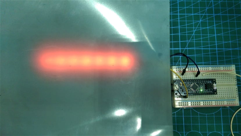
A diffusion sheet about 40mm away from some LEDs
A second method of achieving soft lighting from LEDs which is not as common is to replicate the edge lighting technology used in most LCD screens, this is a trick I learned from DIY Perks on YouTube-.
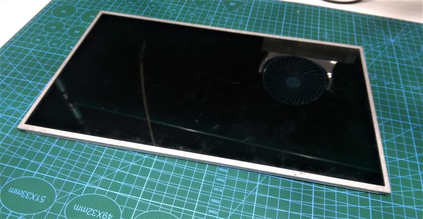
If you have ever taken apart the LCD screen from a laptop, you’ll find a sandwich of different sheets of material that helps to achieve the uniform illumination that backlights the images produced on the LCD.
The first layer is usually a white reflective sheet that also provides a neutral base color for the backlight, this layer is usually followed by a tapered light guide made of PMMA plastic, this light guide will have one of its faces filled with unevenly spaced dots, and is usually lit from its thick side, by a thin fluorescent tube, the light from this tube travels through the light guide and gets reflected by the tiny dots towards the LCD screen, the next layer that follows the light guide is usually a diffusion sheet that blends the dotted light produced from the light guide, and will often be followed by a Brightness Enhancement Film(BEF), the one that looks all funky when you look through it; they look that way because they are specifically designed to create parallel rays of light from a scattered light source, like the light produced from the preceding light guide and diffusion layer; in simpler terms, the BEF layer focuses light forwards. The combination of all these layers will produce extremely soft backlighting in a very thin package.
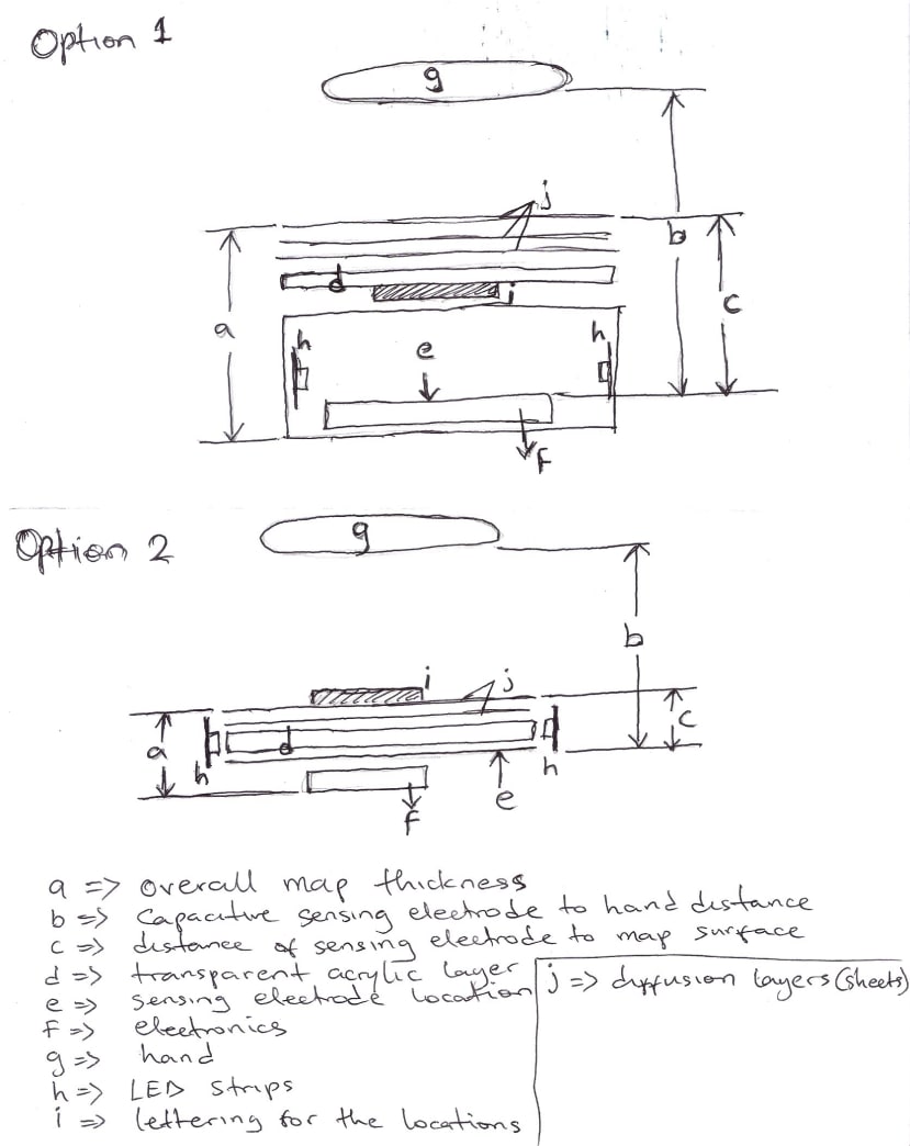
The sketch shown above is my comparison of the two types of soft lighting described above, option 1 which is the traditional soft lightbox will clearly result in a thicker map cell, which is not ideal for a capacitive proximity sensor since the sensing electrode will have to be placed at the base of the cell behind the light source, which means sacrificing some of the already limited proximity range of this types of sensors; on the other hand, an optical proximity sensor which as a longer range will not work so well through the type of diffusion sheets that can produce the required soft lighting. Also, having a thick map cell could make the map as a whole look bulky potentially detracting from its wall art look.
Taking a look at option 2 (LCD edge lighting), it’s kind of perfect for this project: it produces a really soft light, and the resulting cell is going to be very thin which also means that it’s a perfect fit for a capacitive proximity sensor, as the sensing electrode can be placed behind the map’s cells with very little loss in sensing distance and sensitivity, it should also be less complicated wire, the only negative I see is the comparative complexity of having to cut and stack multiple layers of custom shaped map cells, but that's a problem for future me to figure out.
Building a Test Map Cell
The first thing I did was to go out to a local computer repair shop to get a few broken laptop LCD screens, I am going to be getting the reflectors, diffusers, and Brightness enhancement films from them, I won’t be reusing the light guide from the screens as its too thin for the addressable LEDs that will be replacing the thin fluorescent tubes, instead, I will be making a new light guide out of a 2.4mm thick clear acrylic plastic.
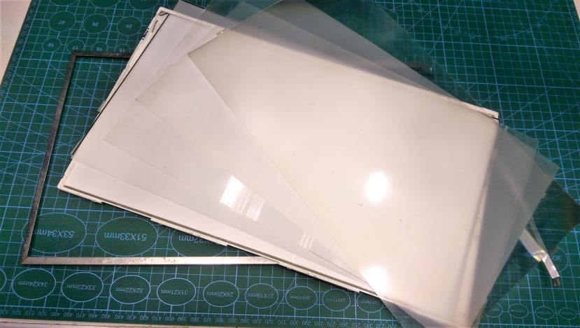
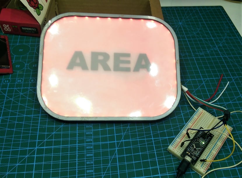
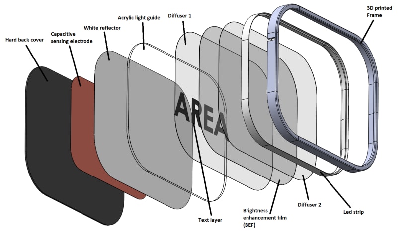
After tearing down one of the screens to reveal the sheets I need, I proceeded to model an enclosure for the sample cell. In this design I replicated the layers just as it was in the screen I took apart, but I replaced the light source with a channel for an led strip all around the edges, and I modeled in the custom acrylic light guide, you’ll also notice a text layer behind some of the diffusion layers, its purpose will be to identify the different areas that will be represented on the air quality map, I am hoping the placement will make the text some worth hidden, so it’s only visible when the cell lights up, it should also make it seem like it's integrated into the cell. The entire thing will be held together in a 3D printed frame.
After 3D printing the test frame, I proceeded to cut the reflector, diffusers, and Brightness enhancement film into the required shape, for the new acrylic light guide, normally the dotted pattern that will guide the light from the edges will be made from a laser cutter or a CNC, but as I don’t currently have those tools, I came up with a hacky solution, using a 38 grit sandpaper, I roughed up one side of the acrylic sheet by sanding a grid pattern onto it.
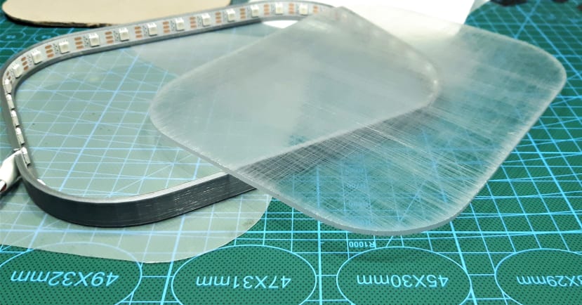
Not the ideal solution, but it works quite well, I won't be doing this for the final map though, for that, I have a much more elaborate plan involving a rotary tool, a flex rotary shaft, and making my 3d printer sad.
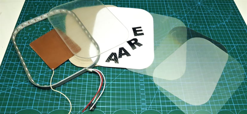
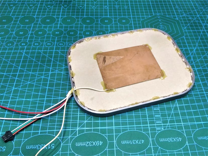
Assembling the cell is pretty straightforward, I installed the LED strip around the frame and then stacked the layers in the appropriate order and with the proper sides facing outwards, the outermost layer is a diffusion sheet, and behind it is the brightness enhancement film, followed by another diffusion sheet, and the text which I cut out of some spare carbon fiber vinyl is the next layer, the acrylic light guide is behind the text, followed by the white reflector sheet. I added strong cardboard to secure all the layers in place, before hot glueing on the capacitive sensing electrode.
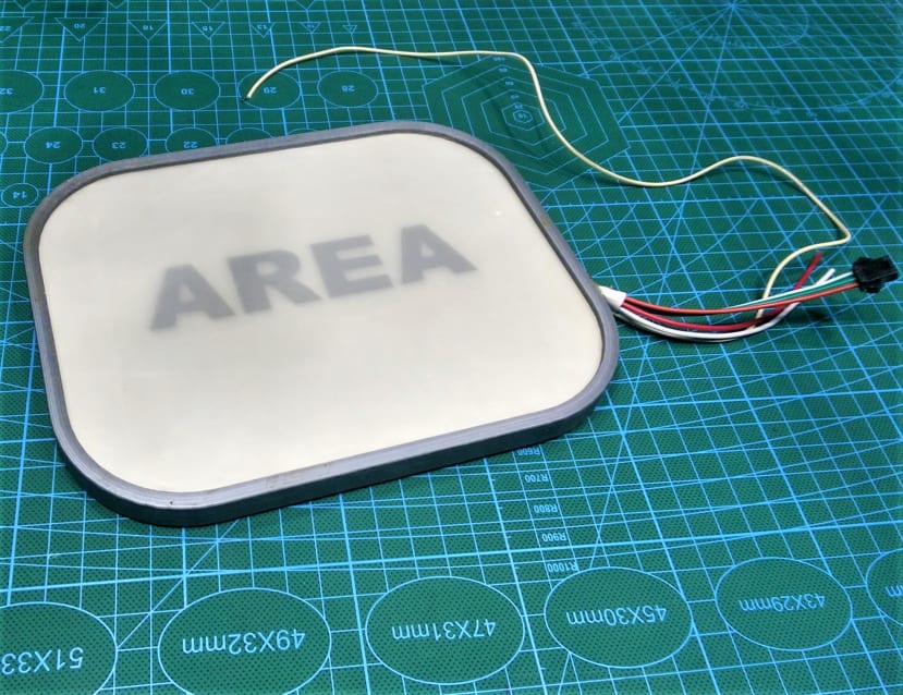
The result is a map cell that’s only 12mm thick, and this is only because I am using a 10mm led strip, if I move to a 4mm thick led strip which I plan to, I should be able to bring the thickness down to about 6mm.
After uploading a simple Arduino sketch to my SAMD21-based board, I can confirm that the cell works as required, the light looks super soft and easy to look at, and I can also activate the capacitive proximity sensor from about 9cm away from the surface.
Connecting to an Air Quality Data Source
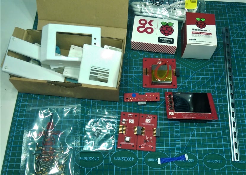
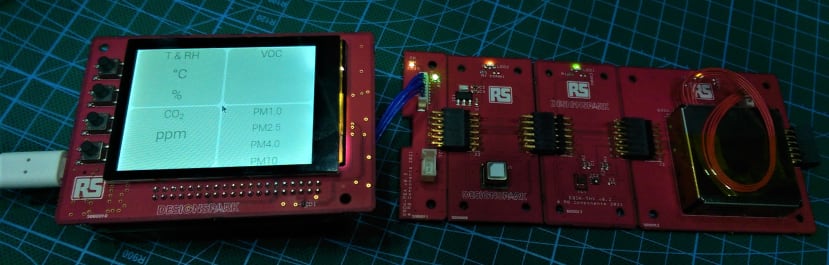
The Air quality sensor kit I am using for this is the Environmental Sensor Development Kit (ESDK) provided by DesignSpark for this project, the kit runs on a Raspberry Pi and features a CO2 sensor, particulate sensor, temperature and humidity sensors and a VOC (volatile organic compound) sensor. The kit is running mosquito MQTT broker so I can extract the sensor data from any MQTT client on my local network.
If you happen to have the same kit, you’ll most likely already have access to the setup documents, but from personal experience, getting the data out of the kit to your respective IoT client devices might not be straightforward, so here are some tips that might help.
- Use the official raspberry pi imager software to burn the provided image to the SD card.
- Make sure you have the 1225 coin cell battery installed on the back of the touchscreen board.
- When you first insert the SD card into the pi, you might find that the sensor data is missing on the screen, that’s probably because, like me, you did not update the code as recommended by the setup instruction.
To solve this:
a. SSH into the raspberry pi and enter the following command lines. (Do this before you customize the configurations in the file at /boot/aq/aq.toml)
-cd aq-device
-git checkout
-git pull
-pip3 install --ignore-installed DesignSpark.ESDK
b. You can then modify the configuration file from the terminal with:
-sudo nano /boot/aq/aq.toml
- To setup your kit to connect to your wifi network:
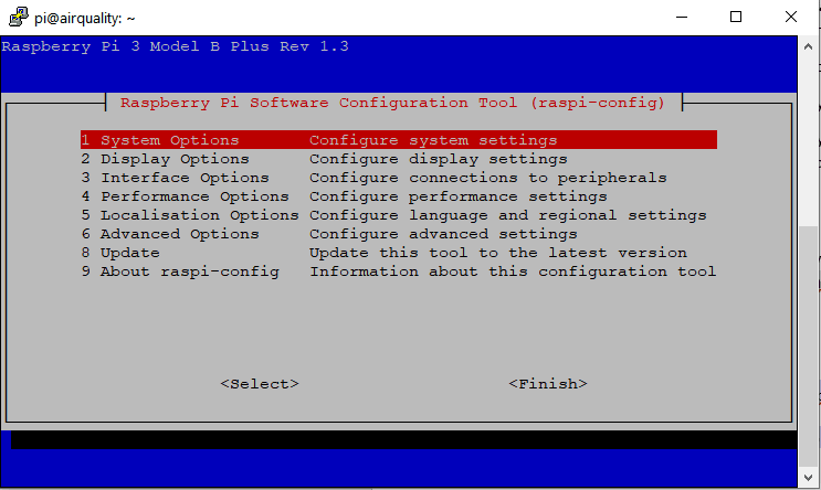
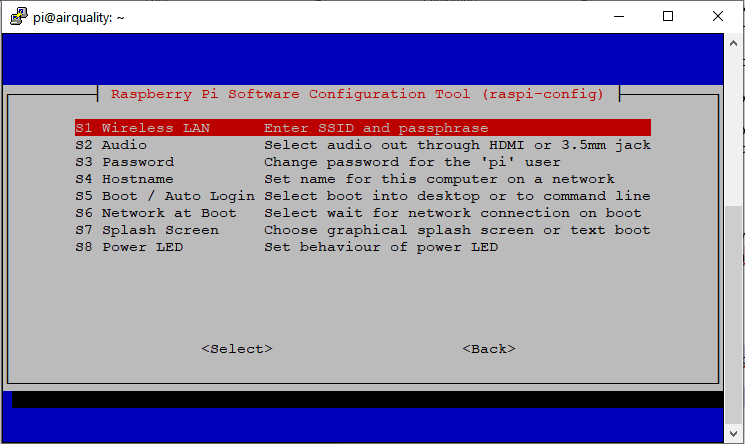
From the terminal, enter the command “sudo raspi-config” and then follow the prompt to add your wifi network.
- Once you’ve successfully setup the kit and you can see the sensor data on the screen, you might find that other MQTT clients on your local network are unable to connect to the server, simply enter the command in the terminal “sudo nano /etc/mosquitto/mosquitto.conf” and add the lines:
listener 1883
allow_anonymous true
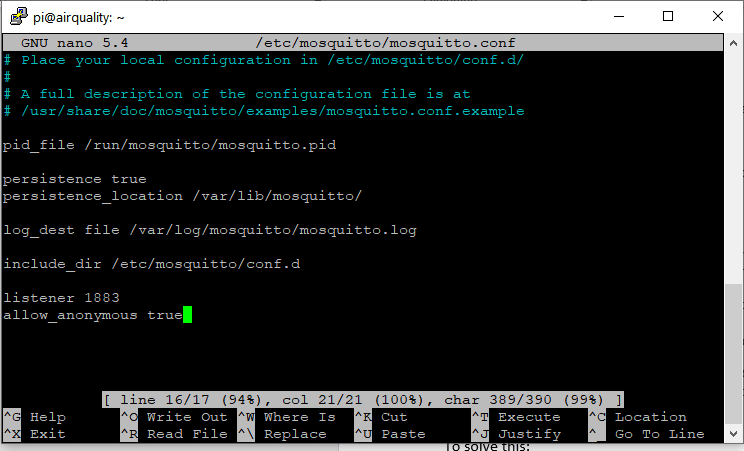
this will allow all MQTT clients to connect without authentication, but if you’ll like to add authentication or allow only specific IP addresses to connect see instructions.
My Test Setup.
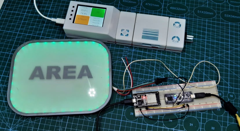
To get the sensor readings from the kit all the way to the map cell controlled by an Arduino, I have an ESP32 board as my MQTT client, its connected to my Wi-Fi network and also connected to the MQTT broker on the raspberry pi which allows me to receive the sensor data from the kit, the data is then forwarded via serial to the wemos samd21 board which is controlling the LEDs on the map cell and running the capacitive proximity sensing code. You can find the code for both boards attached below.
As I mentioned earlier, the kit provides data from a number of sensors, but for this test, I have simply set up my code to respond to the CO2 level alone, in the future I plan to implement a way to cycle through all the data points from the kit.
In the next article, I will look at making the ESDK into a mobile air quality logger.