The Evolution of a Light Theremin
Follow articleHow do you feel about this article? Help us to provide better content for you.
Thank you! Your feedback has been received.
There was a problem submitting your feedback, please try again later.
What do you think of this article?
From learning what a light theremin is to making a custom PCB.
I started out a little over two years ago on work experience, before going on to become a trainee engineer, having decided that I would like to pursue a career in electronic engineering. At work I get to do a wide variety of things, such as laser cutting, assembling kits and even some prototyping. Over the past two years I’ve spent quite a lot of time learning microcontroller basics, mainly working with Arduino and simple projects.
When I first started out I had very little electronics experience – pretty much just a basic understanding of Ohm's law. However, I feel like I’ve learned a lot over the past few years and I'm due to start a HND in electrical and electronic engineering this coming September.
There’s one particular project which follows my progress and it was the very first one I tried my hand at. Over the past two years I've returned to this project a number of times, developing it further and finished with a fully working PCB design. This is the evolution of the light theremin.
What is a light theremin and how does it work?
A light theremin is an instrument that makes a sound, the pitch of which changes based on varying light levels falling on a sensor.
My light theremin used a light-dependant resistor (LDR). This changes resistance according to how much light is falling on it, as light intensity increases resistance decreases and vice versa.
In this light theremin a resistor and an LDR form a voltage divider. An ATMEGA328-PU measures the voltage at this point via one of its analogue input pins. The microcontroller generates a tone, the frequency of is which determined by the voltage, and outputs this to a loudspeaker.
A Novice's Introduction to Arduino
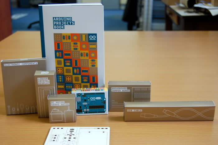
My introduction to Arduino was via the Arduino Starter Kit and I ran through the example projects in the included book – I’d have been completely lost without this.
The sixth project in the book was the first time I had encountered a light theremin. This provided a fantastic tutorial on how to assemble a one on breadboard using an Arduino Uno, 10K resistor, piezo, photoresistor (LDR) and some jumper wires.
Out of all the projects in the Arduino Starter Kit this one jumped out at me and caught my attention the most, so much so that it had a big influence on my following project.
To read more about A Novice's Introduction to Arduino click here
Making a Light Theremin Instrument
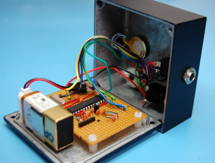
Following my experiences with the Arduino Starter kit I decided that I wanted to have a go at making an improved version of the theremin. This time I used perfboard and a Minimal Shrimp circuit instead of an Arduino, adding some simple improvements also.
One of the big differences between this project and the last were that I drew the schematic myself instead of following a tutorial. Also this theremin would run from a battery supply and have a heavy duty enclosure, so that it could withstand wear and tear similar to what an effect peddle might.
To find out more about this project click here
Getting to know DesignSpark PCB
After enjoying the previous two light theremin projects I decided that I would have a go at making custom PCBs. My initial post about DesignSpark PCB details my first time ever using software for schematic capture and PCB layout.
There was a lot to learn, from how the software works, to how to layout a PCB! It did take me quite a while, but after some time I managed to get the Gerber files for a PCB uploaded to a board manufacturer.
To find out more about this learning process click here
First PCB Project – back to the drawing board
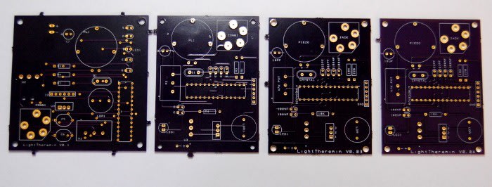
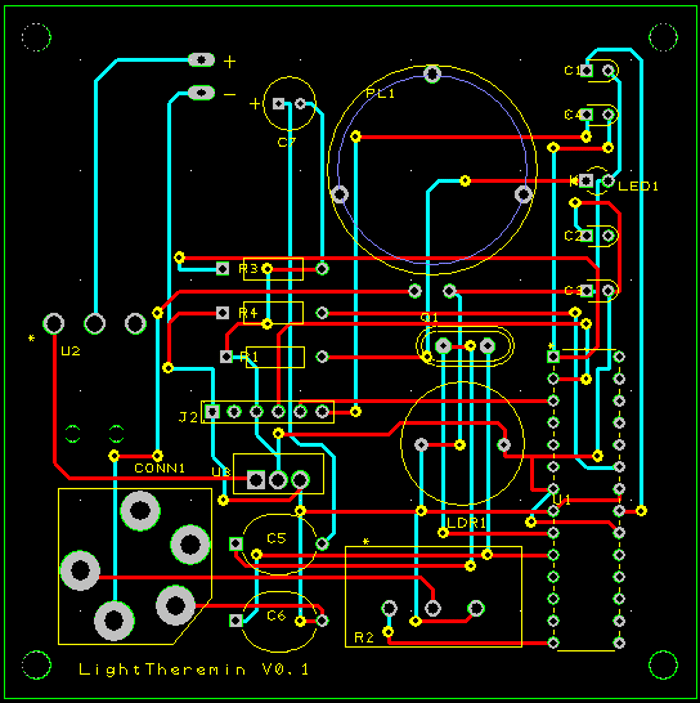
I received V0.1 of the light theremin PCB back from fabrication and assembled the boards. Unfortunately, the boards didn't work as I thought they would, so I had quite a bit of troubleshooting to do to in order to determine the problem.
To read about this stage in the development of the light theremin PCB click here
First PCB Project – Fourth Time Lucky
I fixed the problems identified in V0.1 and sent the new files to fabrication. However, it took another two attempts before I ended up with a board completely free of errors. I learnt a lot in the process and it's very easy to make silly mistakes.
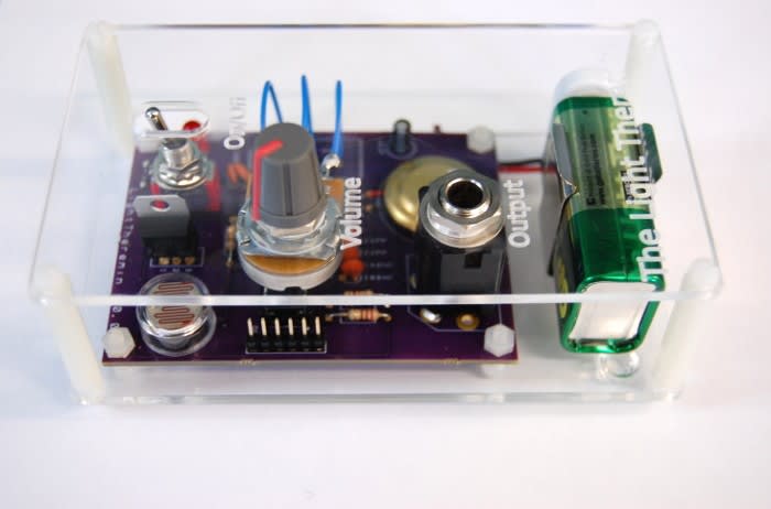
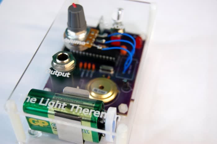
Once I finally achieved a working design I made a custom acrylic case for this.
To learn how I addressed the remaining problems with the PCB click here
6 Posts later...
Over the course of these projects I think its safe to say I've come quite a long way. I’ve made some very silly mistakes, but learned a lot of invaluable lessons. Considering that I was completely thrown in at the deep end with schematic capture and PCB design, having never done this before and learning by experimentation and watching tutorial videos, I don’t think I did bad at all!
If you're interested in building your own light theremin you can find details attached.
Open Source Licence - Solderpad Hardware License v0.51 (SHL v0.51)


