SMT Power on the Board
Follow article
 Dave from DesignSpark
How do you feel about this article? Help us to provide better content for you.
Dave from DesignSpark
Thank you! Your feedback has been received.
Dave from DesignSpark
There was a problem submitting your feedback, please try again later.
Dave from DesignSpark
What do you think of this article?
Surface mounting technology (SMT) has revolutionized the electronics industry. As components such as microprocessors and passives have grown smaller, traditional termination technologies have become too cumbersome to take advantage of miniaturized electronics.

Surface Mount Technology
When printed circuit boards (PCBs) became popular in the 1970s, components would be mounted using through-hole techniques. A hole through the printed circuit board was drilled and plated. The legs of the device were inserted into the PCB and then soldered from behind the board. Initially, this was done by hand, but as electronics entered the mainstream, wave soldering techniques were developed to speed this process and help mass production.
While there is still a place for through-hole termination in small-scale production and prototyping, it has been largely superseded by SMT. Released from the need to provide adequate spacing between through-hole soldering, SMT allows the designer to take advantage of the latest generation of small components. Whereas the pitch (the distance between pins) of through-hole components would normally be around 2.54mm (0.100”), surface mount devices can use a pitch of as little as 0.3mm (0.012”). This allows many more parts to be placed on a PCB, achieving a greater component density.
Surface mounting also allows designers to utilize both sides of a PCB as they do not need to allow room for holes and solder on the back of the board. This further increases the component density and allows engineers to pack more features and capabilities into their products.
Surface mounting does present a few challenges, however. Besides the need for improved accuracy during the manufacturing process, one of the largest concerns is how to provide power to the PCB. Power connections are far larger than those of electronic signals due to the increase in energy that must pass through them. To keep electrical resistances low, and prevent dangerous increases in temperature, power connections are large and do not lend themselves well to surface mounting.
This has become increasingly important over the last few years as the number of applications that require power to be connected to PCBs has risen dramatically.
Power in Automotive Applications
The growth of the electric vehicle market has been rapid over the last decade. The rising cost of conventional vehicles, both economically and environmentally, has driven electric vehicles into the headlines. When designing the PCBs for this new breed of electric vehicles, engineers are faced with power demands that are on a completely different scale to traditional electronic designs. The electric motors that drive these vehicles have current ratings of hundreds of amps.

Electric vehicles on modern city streets
The increase in power load is not unique to electric vehicles. Modern vehicles are packed with electronic systems. Many vehicles no longer employ mechanical controls for a wide array of systems and instead use fly-by-wire techniques that have more in common with those of military aircraft than family cars. Equipment that we now take for granted, such as navigation, climate control, and on-board entertainment, are all adding to power needs, whether for family cars or agricultural vehicles.
Saving the Planet
Domestic energy production has become another concern, and consumers are increasingly questioning the environmental impact of the electricity that they use. This has led producers to find alternative ways to generate the power that we use in our homes. Wind and solar energy are all becoming more popular, as is microgeneration – using the latest technology to create electricity locally. However, the huge range of electronics found in the modern home means that the flow and quality of the electricity must be tightly regulated to prevent damage to sensitive equipment. This is all being performed by the latest PCB designs.
There is a growing need to provide power connections to printed circuit boards, but we have already seen that surface mounting is not suitable for high-power applications. To create a connection capable of handling sufficient power whilst providing a reliable mechanical joint, designers are combining the best attributes of through-hole with the convenience of surface-mount techniques.
Alternative to Surface Mount
The THR termination method uses a through-hole terminal which is compatible with the reflow soldering process of surface mount. This means that THR components can be placed at the same time as the SMT components, and still allows two-sided PCBs. A properly terminated THR terminal that passes through the PCB provides both an enhanced contact area to keep the resistance low. In addition, a reliable mechanical connection is created to allow large diameter cables to be used for power connection.
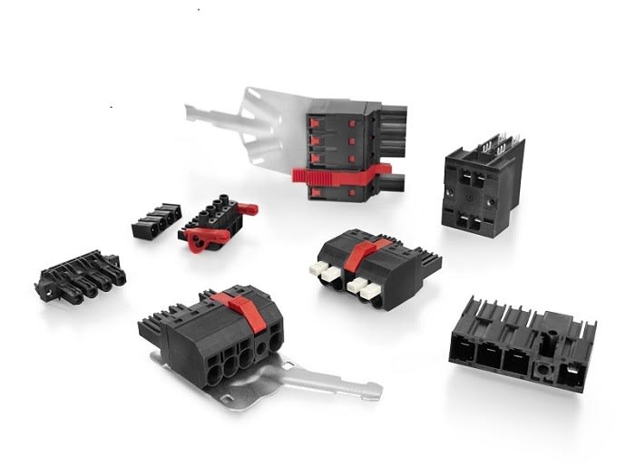
OMNIMATE from Weidmuller
The latest OMNIMATE PCB-mounted terminals (172-2574) from manufacturer Weidmüller combine THR termination with easy-to-use PUSH-IN cable clamps. This simple, tool-free cable insertion provides a secure joint whilst reducing installation costs.
To view the latest products from the OMNIMATE range, and other products from the Weidmüller range, click here.