Self-Excitation Analysis in Operational Amplifier Oscillation
Follow article
 Dave from DesignSpark
How do you feel about this article? Help us to provide better content for you.
Dave from DesignSpark
Thank you! Your feedback has been received.
Dave from DesignSpark
There was a problem submitting your feedback, please try again later.
Dave from DesignSpark
What do you think of this article?
1 Introduction
Op-amp is a device with a wide range of uses. It can be used as a precision AC and DC amplifier, active filter, oscillator, and voltage comparator when connected to an appropriate feedback network. You might ignore that op-amp oscillation is easy to self-excited. Why and how to deal with it? Just follow the analyses below.
2 Two Important Parameters
Closed-loop gain G=A/(1+FA)
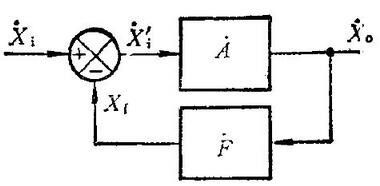
Fig 1. Simple Diagram
Where A is the open-loop gain, F is the feedback coefficient, and AF is the loop gain.
A (open loop gain) = Xo/Xi
F (feedback factor) = Xf/Xo
3 Why the Op-Amp Oscillates and Self-Excites
1) The loop gain is greater than 1 (|AF|>1)
2) The phase difference between the signals before and after feedback is more than 360 degrees, which means that positive feedback can be formed.
In the case of a negative feedback circuit, the smaller the feedback coefficient F, the less likely it is that self-oscillation will not occur. In other words, the greater the F (that is, the greater the amount of feedback), the greater the possibility of self-excited oscillation. For the resistance feedback network, the maximum value of F is 1. If an amplifying circuit does not produce self-oscillation when F=1, it will not produce self-oscillation for other resistance feedback circuits. A typical circuit with F=1 is a voltage follower circuit. Therefore, during work, the op-amp is often connected to the form of a follower for testing, and if there is no self-excitation, then it is connected to the actual circuit.
The cause of self-oscillation is mainly because the integrated operational amplifier is composed of multi-stage DC amplifiers. Because the output of each amplifier and the input of the subsequent amplifier have output impedance, input impedance and distributed capacitance, so there is an RC phase shift network between the stages. When the signal passes through the first-level RC network, an additional phase shift will be generated. In addition, the external bias resistance and input capacitance, the output resistance, the capacitive load feedback capacitance, and the common internal resistance of the multi-level op-amp through the power supply, even the distributed inductance on the power line, poor grounding, etc. coupling, can form additional phase shift. The signal output by the op-amp is superimposed to an additional phase shift of 180 degrees through the negative feedback loop. If the feedback amount is large enough, the negative feedback will eventually be transformed into positive feedback, which will cause oscillation.
4 Important Concepts
4.1 Phase Margin
As shown in the figure below, obviously we are more concerned about whether the phase shift exceeds 180 when 20lg|AF|=0.
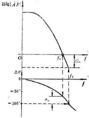
Fig 2. Schematic Diagram of Stability Margin
4.2 Causes of Op-Amp Shock
1)The op-amp oscillation may be caused by distributed capacitance and inductance.
M: Capacitors can be connected in parallel at the feedback end to offset the impact.
2) The capacitive load is driven by the op-amp.
M: You can connect a resistor to the output of the op-amp first, and then connect the load.
3) It may be caused by too deep feedback.
M: Reduce the loop gain and the amount of feedback, that is, increasing the closed-loop gain. For example, the op-amp is easy to oscillate as a voltage follower. Increase the magnification and the oscillation will disappear.
4.3 Solutions
a. In-Loop Compensation
Op-amp feedback resistor connected in parallel with feedback capacitor: phase lead compensation.
As shown in the figure below, it is obvious that the frequency of 0dB is shifted back after compensation, and the bandwidth of the op-amp is enlarged, that is, the frequency point of self-excitation is shifted back.
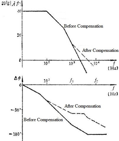
Fig 3. Frequency Characteristics of Lead Compensation
Small capacitors are called phase-shifting capacitors. To prevent self-excitation of the op-amp is generally from a few picofarads to tens of picofarads to hundreds of picofarads, depending on the working frequency and the model of the op-amp. Simply put, the larger the added capacitance, the narrower the bandwidth.
Prevent the oscillation Rf from forming a pole with the input capacitance and stray capacitance of the op-amp. If the pole is within the frequency range used by the op-amp, it may cause the op-amp to oscillate. After adding Cf, Cf and Rf produce zero points to offset the pole. The general value is Cf>Ci, where Ci is the input capacitance of the op-amp and the total stray capacitance of the input pin.
b. Out-of-Loop Compensation
Connect a small resistor in series to the output terminal of the op-amp, and then connect it to the subsequent stage. It can be between ten ohms and tens of ohms. The specific value is related to the input capacitance of the subsequent stage circuit. You can try different resistance values to obtain stability of the output.
Considering that the load has a little capacitance (CL), the loop gain is reduced under the effect of the output resistance and CL. At the same time, there is no longer a proportional relationship between the phase and the gain, and the phase lag becomes a decisive factor, which makes the feedback loop lose stability and may cause oscillations at the worst. Therefore, a small resistor R is connected to the output of the op-amp to eliminate the phase lag of the feedback loop caused by CL.
c. Note
1) The power supply is stable, preferably connects with 0.1uf, 10uf capacitors in parallel.
2) The magnification should not be too large, and the number of magnification levels should not exceed four.
5 Principle of Oscillation
Before experiment or test, if you use an oscilloscope to connect to the output of the op-amp, you can sometimes see a waveform with a higher frequency and similar to a sine wave, and occasionally low-frequency oscillations occur. Different methods can be used to solve the problem according to the principle of oscillation.
(1) Whether the feedback polarity is wrong or the negative feedback is too strong. If the negative feedback is wrongly connected to the positive feedback, it is very easy to produce oscillation. In addition, the stronger the negative feedback, the easier it is to produce self-excitation.
(2) If there is a capacitive load connected to the output terminal since it strengthens the phase shift of the circuit, easier to result in self-excitation. Another RC link can be used to compensate for the phase shift. If the compensation is good, the self-excited oscillation will be eliminated.
(3) Wiring stray capacitance is too large. When the input loop is high impedance, the hysteresis link composed of the stray capacitance and resistance between the wiring and the ground or between the wiring will make the component unstable. To this end, a capacitor CF can be connected in parallel at both ends of Rf (feedback resistance), or an RC branch can be connected in parallel at the input end of the operational amplifier. These two links belong to the nature of lead correction, that is, the phase lead effect they produce may offset the phase lag effect caused by the aforementioned stray capacitance, so that the op-amp is stable.
(4) Insufficient bypass measures for power wiring. Power leads not only have a certain resistance, but also a certain inductance and distributed capacitance. Therefore, when many op-amps are connected to the same power line, these factors will affect each other. The solution is to connect tens of uF electrolytic capacitors and 0.01 uF ceramic capacitors in parallel between the terminals of the positive and negative power supplies on the printed circuit board socket and the ground. If the operational amplifier is used as a broadband amplifier, capacitor with low inductance must be selected.