Selecting the Ideal LCD Display for an EVE Enabled Design
Follow article Dave from DesignSpark
How do you feel about this article? Help us to provide better content for you.
Dave from DesignSpark
Thank you! Your feedback has been received.
Dave from DesignSpark
There was a problem submitting your feedback, please try again later.
Dave from DesignSpark
What do you think of this article?
There are a number of key parameters that must be considered when implementing an LCD into a system design. With regards to the display itself, the key parameters include size, resolution, brightness, touch control and the exposed interface to the system controller. From a system perspective, the choices are often driven by the system MCU and available memory. A number of engineers prefer the one-chip solution to control the system and the display, whilst others prefer to partition the design to have an MCU or controller dedicated to the system tasks and offload the graphics control to a separate IC. Of course, there are both benefits and drawbacks to be found in both methodologies.
This article looks primarily at the key parameters which should be considered when selecting a display and creating a system based on the EVE FT8xx series of graphics controllers.
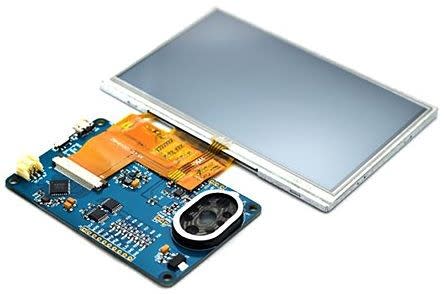
Bridgetek FT810 EVE Credit Card 5in Resistive Touch Screen Module
(901-5073)
Display Size
The size of a display is one key factor in defining the user experience. It is a limiting factor in the number of icons or objects that can be simultaneously displayed, and also affects the size of icons or buttons that may be present in a touch controller. The size is typically defined in inches and taken as a measurement of the distance between diagonally opposite corners. However, we are now seeing more variations such as circular displays available in the market, primarily driven by the smartwatch industry.
Most manufactured displays conform to a standard size as seen in the figure below:

Figure 1: Standard Screen Sizes
Display Resolution
Complementing the display size is the display resolution. This is the definition of the number of pixels available. The figure will be quoted as a number of pixels in the x-direction followed by a number of pixels in the y-direction, which also allows for users to identify displays that are natively landscape (x- direction is the bigger number) or portrait (x- direction is the smaller number). Some controllers will assist with easy rotation - such as the Bridgetek FT81x series.
In general, the larger the display size, the greater the resolution or number of pixels. However, it is possible to have the same quoted resolution on different sized displays. What this really means is that the pixels will be more spaced out on the larger displays. With EVE graphics controllers, the maximum resolution is 800 x 600 pixels.
Display Interface
The interface that the display uses to connect to the system is a critical factor in selecting a suitable display. The first choice may be whether the system can control a parallel or serial interface and what the voltage levels will be. Most of the smaller displays that Bridgetek can support have RGB support. For larger displays, care must be taken to select a display with RGB interfacing as opposed to LVDS or other formats.
Display Interface Timing
The timing of a display will be largely fixed and defined by its resolution. For maximum flexibility, it is important that the display controller has programmable timing to enable support for different screen sizes and orientations.
Figure 2: Display Timing Parameters
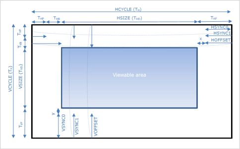

Figure 3: EVE Timing Registers
The timing parameters in a typical display are there to define the speed of the horizontal and vertical sync signals. The timing will allow for a blank (non-visible) border. In analogue CRT technology, this blanking period was used to allow the scanning beam to return to the start of a line or frame.
Note that with EVE and LCD technology, timing is simplified slightly, as all images are drawn with a progressive scan as opposed to an interlaced scan (as was used in many older analogue televisions and displays).
Another clock - the Pixel clock (PCLK) will be the fastest clock output to the display, will clock every single pixel output, and may be of either polarity so the controller should match the display requirements. Bridgetek’s FT8xx solutions allow this polarity to be switched as required by the display, which will also help define the refresh rate e.g. PCLK / resolution = frame rate e.g. 9.6MHz / (800 x 480) = 25 frames per second. A 9.6MHz PCLK is easily achieved with the FT8xx, by dividing the internal 48MHz core clock by 5 (REG_PCLK).
Touch control
Touch control on a display module is enabled by adding an additional membrane over the visible display. The choice of touch control has an impact on screen brightness, functionality, interfacing and cost. The 3 main choices are NONE, RESISTIVE, CAPACITIVE which are explained in full detail below.
NONE:
This is the most inexpensive option. The display module does not need to include an additional element, and there is no additional interface to add to the system. These displays are ideal for when there is no user interaction in the system, such as a simple advertising screen, or in scenarios where physical buttons are required for safety or accessibility reasons.
RESISTIVE:
Resistive displays are next in line for both cost and functionality. They offer a robust touch experience, whereby the display must be physically touched to deform the touch membrane. They are a little simpler than capacitive touch solutions, in that the interface is typically a standard 4 or 5 wire interface providing X+, X-, Y+, Y- data to determine the coordinate of the touch point. A limitation of the resistive touch solution is that only one touch point may be correctly reported at a time. Additionally, with this technology, the maximum brightness provided may be less than options with no touch or capacitive touch, due to the construction of the layers. Resistive touch control is ideal for simple menu driven displays, where a user may select individual buttons to select equipment functionality such as selecting a drink from a coffee machine or as a keypad for unlocking doors etc.
CAPACITIVE:
Capacitive touch display is the premium solution. This extends the capability of the resistive touch controller to allow for multiple touch points to be correctly reported simultaneously. In functional terms, this means that a user may add gesture control to the basic touch for functions such as pinch and zoom for images. Like-for-like displays with a capacitive touch layer tend to be brighter than the resistive versions. However, all these great enhancements come at a cost – both financially and in terms of complexity. Capacitive touch controlled displays usually have a dedicated touch control module which is accessed over I²C. This is not necessarily an issue, however, it should be noted that there are multiple touch control modules on the market, and they do not all use the same protocol. As such, from a software perspective, the user may require different drivers for different displays, which is an issue that is not present with no touch or resistive touch displays. With EVE, the FT8xx solution, provision has been made to support some controllers natively whilst providing a “host” mode to bypass the internal drivers and allow support for newer models. Full details are available in the FT8xx datasheets from Bridgetek.
Using Touch Co-ordinates
Using touch coordinates requires some mathematical work. As can be seen from figure 4, a button covers a large area or number of touch coordinates, whilst the touch event reports only one coordinate. Determining which button a touchpoint relates to could potentially use up a lot of MCU resources.
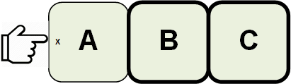
Figure 4: Relating a touch point to an area or visible object
With the EVE solution, the FT8xx chip completes the complex algorithm, leaving the system MCU to focus on other tasks. The FT8xx treats all visible items placed on the display as objects and each object may be given a unique TAG value. When the FT8xx detects a touch event, it calculates where the touch occurred in relation to visible objects and returns a TAG value to the system MCU. The system MCU may then simply use the TAG value as an interrupt to perform a task based on the button press identified by its TAG.
Assembling the EVE system
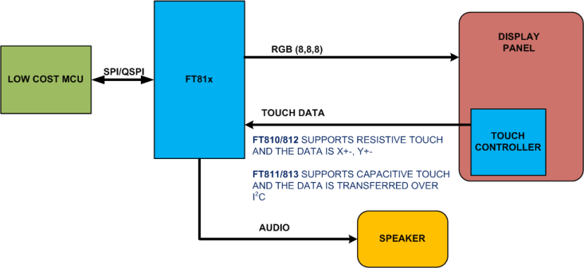
Figure 5: Basic EVE System
The EVE solution to creating a display enabled system offers great flexibility:
- The chip acts as an SPI bridge between the system MCU and the display
- The chip does the majority of the graphics and touch control work
These two factors alone should allow a new market of products which were not capable of supporting full-colour TFT displays with touch control to access these features, without the need for expensive or complex system MCUs.
Also notable from the block diagram is that there is no expensive flash memory. This is another key element of the EVE solution, as by drawing images line by line, use of system memory is optimised.
Finally, ease of programmability and maintenance is upheld by using an object-oriented approach where items are simply defined in a display list (WHAT, WHERE, SIZE, COLOUR) for processing by the FT81x.
Full details of the EVE FT8xx solutions are available in the supporting datasheets and programming guides available on the Bridgetek website, www.brtchip.com.