SCaRRob - A UKSEDS Olympus Rover Trials Entry
Follow article Dave from DesignSpark
How do you feel about this article? Help us to provide better content for you.
Dave from DesignSpark
Thank you! Your feedback has been received.
Dave from DesignSpark
There was a problem submitting your feedback, please try again later.
Dave from DesignSpark
What do you think of this article?
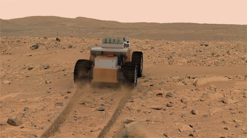
Throughout my time at University, I have been heavily involved in our Space Society and have led multiple teams entering the UKSEDS Olympus Rover Trials competition. This competition, organised by UK Students for the Exploration and Discovery of Space (UKSEDS) aims to inspire students to pursue careers in the space industry, especially in the areas of engineering and robotics. The competition's mission this year was to design rovers capable of collecting small cylindrical sample canisters. This is a scaled-down version of the mission the Rosalind Franklin Rover will perform. The rovers are limited to a 5kg mass, and the competition is held at Airbus’s Mars Yard Facility. Following this, the rovers must survive a simulated rocket launch vibration test at RAL Space.
I opted to build an individual entry for the competition as my final year project for my mechanical engineering degree. I was keen to apply the lessons learnt from previous years into a more refined solution. Primarily I sought to minimise the rover’s size, equip it with a more advanced payload system, and improve the off-road mobility.
For the rover’s arm, a multi-degree of freedom design was constructed from 3D printed linkages, and operated via servos, with a claw end effector. The arm has 2 primary linkages with an elbow link allowing it to rotate 360 degrees. The “hand” is also articulated about its wrist and has a Pi Zero Cam as the rover’s vision mounted to it for clear viewing of the canisters. The arm translates left and right using an IGUS slide rail and is driven by a servo-operated rack. Upon collecting a canister, the arm folds back allowing it to be stored in the hopper.

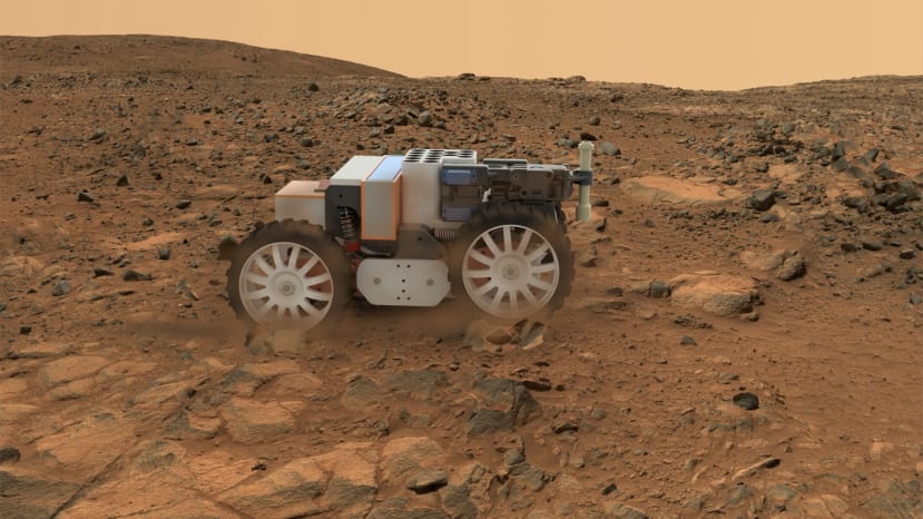
The rover drives on a 4x4 wheeled arrangement. Mounted in the centre of the rover is an aluminium U channel to which 4 motors mount. The aluminium channel provides the mounting point for the vibration test and so reduces the number of primary load-bearing components by attaching the motors directly to the base, thus saving mass. Power is transmitted from the motors via bevel gears and then timing belts to the wheels. Suspension is provided via a simple swing arm arrangement which can be constructed to be very durable for the vibration test. The swing arms articulate around the driven shafts with the timing belts running along the inside. This is a very compact arrangement with minimal modes of failure. Once again, the suspension arm utilises IGUS bearings, where the lubricant-free assembly will be ideal in the sandy environment.
The rover is primarily constructed out of 3D printed parts and laser-cut acrylic to a modular design. To the rear mounts an electronics box containing a Raspberry Pi Zero 2 and motor and servo control boards. In front of this is the battery compartment, and at the front the payload system mounts. This is constructed on an acrylic base so can easily be swapped out for different missions and design revisions, all fitting within a rectangular envelope.
One concern for rovers with lots of moving parts such as arms or suspension is how they will fare in the vibration test. However, the rover has been designed so that as it is bolted down, the swing arms move up against bump stops locking them down. The arm moving up also stops any lateral motion of the arm, and with the help of a locking plate secures it firmly down.
Later in the summer, I’ll post an update to this once the rover is built and tested, and hopefully get some design guides and code made available too.
Firstly, I’d like to thank the University of Bath for their support of me throughout this project. Secondly IGUS for supplying me with their bearings. But finally, RS Grassroots Student Project fund made this possible, and so a final massive thank you to them.