Prototyping LoRa Wireless Monitoring with XinaBox Part 3: Adding I/O and Testing
Follow article
 Dave from DesignSpark
How do you feel about this article? Help us to provide better content for you.
Dave from DesignSpark
Thank you! Your feedback has been received.
Dave from DesignSpark
There was a problem submitting your feedback, please try again later.
Dave from DesignSpark
What do you think of this article?
Rapid prototyping a long-range wireless sensor system with the modular electronics platform.
In part 1 we outlined our use case and took a look at LoRa wireless modulation, giving our rationale for using this, before then exploring some of the XinaBox hardware options available. In Part 2 we moved on to programming a CR02 module or “☒CHIP” — which features an integrated microcontroller and radio — and then sending and receiving data across a LoRa wireless link.
In this third and final post, we add a temperature sensor for input at the transmit side of the wireless link, with a “photorelay” for driving an indicator or alarm sounder output on the receiving side.
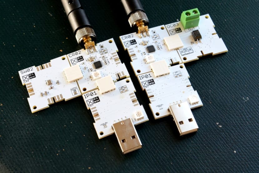
Hardware used

We’ll be using the same CR02 modules for the microcontroller plus LoRa, with IP01 USB-UART modules for programming and testing.
The sensor module we’ll be using is the XinaBox SW02 (174-3745) . This integrates a Bosch BME680, which is, in fact, a combined temperature, humidity, air pressure, and volatile organic compounds (VOCs) sensor. However, in this example we will just be using it to measure temperature, as with this we can much more easily trigger change during testing.
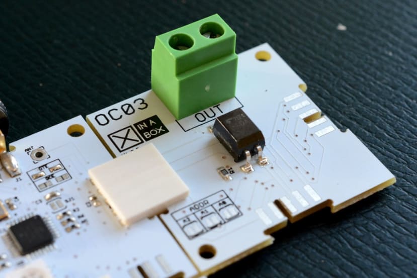
For the output, we’ll be using an XinaBox OC03 (174-3715) . This provides optically isolated control of a relay and is able to switch loads of up to 40V at 2A. As such it could be used to directly switch a standard industrial indicator or buzzer etc. which generally operate on 24V, or alternatively, it could be used to control and 12 or 24V relay which in turn switches mains.
Together with two CR02 (174-3699) modules, these will allow us to monitor the environment and when the temperature at a remote location falls outside a given set point, raise the alarm.
Arduino libraries
In the previous post, we installed the RadioHead library in order to add support to the Arduino IDE for the CR02 LoRa radio. To use the SW02 and OC03 modules we will also need to install:
The quickest way to install these is to download a ZIP file for each and then in the Arduino IDE, select Sketch → Include Library → Add .ZIP Library... After restarting the IDE there should then be new example sketches available via File → Examples → Examples from Custom Libraries.
Hardware test

So first we need to ensure that from the Tools menu we have selected:
- Board: Arduino Pro or Pro Mini
- Processor: ATmega328P (5V, 16MHz)
- Port: /dev/ttyUSB0 (or whatever the IP01 has enumerated as)
If we then load the example, SW02_Temperature_Measurement, compile/verify this, upload and then open the Serial Monitor, we should get temperature readings printed out.
To test our output module we can load the example, OC03_ToggleOutput, compile and upload this, then again open the Serial Monitor. This time we will just get the message, OC03 Test, printed out. If we measure the resistance across the output terminals we should see that the photorelay is closing for 2s, opening for 2s, and then repeating.
So now we have our development environment set up and have verified the hardware is working, let’s move on to integrating the I/O with LoRa transmit and receive.
Sensor plus transmit
#include <xCore.h>
#include <xSW02.h>
#include <RH_RF95.h>

#define LED_BUILTIN 16
#define CR02_FREQUENCY 868.0

const int DELAY_TIME = 2000;
const float MAX_TEMP = 30.00;

xSW02 SW02;
RH_RF95 CR02;

void setup(){
  pinMode(LED_BUILTIN, OUTPUT);
  Serial.begin(115200);

  // SW02 sensor setup
  Wire.begin();
  SW02.begin();

  // CR02 radio setup
  if (!CR02.init()){
    Serial.println("CRO2 init failed");
  }
  CR02.setFrequency(CR02_FREQUENCY);
  CR02.setTxPower(23, false);

  // Delay for sensor to normalise
  delay(5000);
}

void loop(){
  float temp;
  byte txdata[1];

  // Read SW02 sensor
  SW02.poll();
  temp = SW02.getTempC();

  // Print temperature to the Serial Monitor
  Serial.print(temp);
  Serial.println(" C");

  // Set status (0x00 if temp OK and 0x01 if high)
  if (temp <= MAX_TEMP) {
    digitalWrite(LED_BUILTIN, LOW);
    txdata[0] = { 0x00 };
  }
  else {
    digitalWrite(LED_BUILTIN, HIGH);
    txdata[0] = { 0x01 };
  }

  // Transmit status
  CR02.send(txdata, sizeof(txdata));

  // Delay between sensor reads
  delay(DELAY_TIME);
}
In the above sketch we:
- Include the libraries we need and configure some parameters
- Set up the CR02 LED, sensor and LoRa radio
- Get the temperature and then print this out to the serial port
- Set the status variable to 0 if the temp is OK and to 1 if the set point has been exceeded
- Transmit the status over our LoRa link
- Wait for the configured delay time and repeat from step 3
Now we could have transmitted the actual temperature reading and that might be useful if we wanted to be able to configure the set point at the receiving end. However, evaluating the temperature on the transmit side offers certain benefits too. For example, we could if we wanted to have the sensor transmit only when the temperature limit is exceeded, or to signal the alarm as soon as this happens and otherwise transmit a status “heartbeat” at a less regular frequency.
Also note how we are just transmitting a single byte, where 0x00 means everything is OK and 0x01 means the temperature is too high. We could also have lots of additional status types, e.g. 0x03 for when we fail to read the sensor and perhaps 0x04 for the batteries are low.
Generally speaking, it is best to spend as little time on air as possible — hence transmit as little data as possible — so as to conserve energy and use of wireless spectrum. This is why we are transmitting just a single status byte over the radio link, instead of needlessly verbose and wasteful ASCII text such as “alarm” or “temperature is 27C” etc.
Receive plus output
#include <RH_RF95.h>
#include <xOC03.h>
#include <xCore.h>

#define LED_BUILTIN 16
#define CR02_FREQUENCY 868.0

RH_RF95 CR02;
xOC03 OC03;

void setup()
{
  pinMode(LED_BUILTIN, OUTPUT);
  Serial.begin(115200);

  // CR02 radio setup
  if (!CR02.init()) {
    Serial.println("init failed");
  }
  CR02.setFrequency(CR02_FREQUENCY);
  CR02.setTxPower(23, false);

  // OC03 setup
  Wire.begin();
  OC03.begin();
}

void loop() {
  byte buf[1];
  byte len = 1;

  if (CR02.available())
  {
    if (CR02.recv(buf, &len))
    {
      Serial.print("Status: ");

      if (buf[0] == 0x00) {
        Serial.print("OK");
        OC03.write(LOW);
        digitalWrite(LED_BUILTIN, LOW);
      }
      else if (buf[0] == 0x01) {
        Serial.print("ALARM");
        OC03.write(HIGH);
        digitalWrite(LED_BUILTIN, HIGH);
      }
      else {
        Serial.print("ERROR - unknown status");
      }
      Serial.print("   //   RSSI: ");
      Serial.println(CR02.lastRssi(), DEC);
    }
    else
    {
      Serial.println("Receive failed!");
    }
  }
}
On the receiving node we:
- Include the libraries we need and configure some parameters
- Set up the CR02 built-in LED and LoRa radio, plus OC03 module
- Look for incoming data
- Parse the status
- Print out to the terminal and set the photorelay and built-in LED
- Go back to step 3

We also print out the Received Signal Strength Indication (RSSI) to the Serial Monitor, as this is quite handy to have and gives an indication of the radio link quality. During commissioning if the signal is too low, we might increase the LoRa spreading factor (SF) on the transmit side, which would give us greater range at the cost of more time on air transmitting. If we monitored the RSSI over time and it degraded, it could mean low batteries, that an obstacle has moved into the radio path, or that there is some sort of hardware issue, such as a broken antenna.
Summing up
While this is an extremely simple example, it demonstrates how we can very quickly prototype a long-range wireless monitoring solution that doesn’t relay on existing networks, or additional base stations or gateways. In this case, integrating a BME680 sensor for temperature measurement and which is also capable of measuring much more than this. In addition to which there are many other xCHIP modules that we could select from for input or output, with these all benefiting from quick and easy physical interconnection via xBUS connectors.