Practical tips for testing fiber optic power measurement
Follow articleHow do you feel about this article? Help us to provide better content for you.
Thank you! Your feedback has been received.
There was a problem submitting your feedback, please try again later.
What do you think of this article?
As many of us are no doubt aware, optical fiber is an excellent medium for the transmission of data through light signals travelling down the length of the glass fiber. Super-fast, flexible and thin, fiber optic cable rarely needs amplification, even over long distance transmissions. But for all the obvious benefits of fiber over the drawbacks of traditional copper wiring, it can be a challenging material for network engineers to get to grips with.
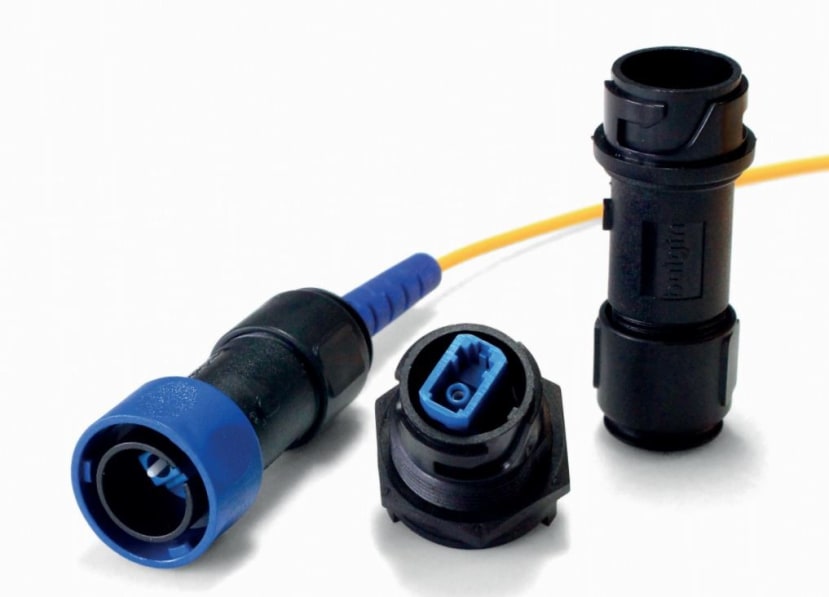
4000 Series - Simplex LC Fiber Buccaneer
The most basic form of fiber optic performance assessment is measuring the optical power that is emitted from the end of the fiber, which is measured in decibels (dB). To best understand the power measurement, it can be looked at in terms of optical loss. Splitters, fusion splices, connectors and other intermediary network components can all contribute to attenuation in signal, otherwise known as insertion loss (IL).
Balancing the “budgets”
If you’re new to working with fiber optics, you may often come across the terms “power budget” and “loss budget”, so it’s important to understand the difference between the two. The term power budget refers to the maximum amount of loss that an entire datalink (from transmitter to receiver) can tolerate in order to operate properly. Sometimes you might find that the power budget has both a minimum and maximum value. This means it needs at least a minimum value of loss so that the receiver doesn’t get overloaded, whereas the maximum value of loss will ensure that the receiver has sufficient signal to operate on.
The loss budget is the total amount of loss that your endpoint should have. To calculate this, you’ll need to add up the estimated average losses of all the components used in your cable plant to get the estimated total end-to-end loss. This figure is then compared to the start point at the network’s data source to determine whether or not the cable is functioning optimally.
Tools you’ll need
In order to measure power, continuity and loss in a fiber optic cable, a light source and a power meter are required. Before using a power meter in the field, read the manual and run some practice tests. Make sure you have the proper safety equipment such as eye protection before testing fiber optic cables with a power meter. You may also need reference test cables, mating adaptors, a visual fault locator and a fiber optic cleaning kit to keep the tiny, hair-like cable ends safe from contamination, particularly in outdoor or industrial environments.
While optical power meters are the most basic of power measurement instruments for fiber, optical loss test sets (OLTSs) and optical time domain reflectometers (OTDRs) are also useful tools for accurately measuring power in testing loss, particularly in outdoor installations.
Using the power meter
When measuring fiber optic power with a power meter, attach the meter to the cable. Fiber optic power meters have inputs for attaching fiber optic connectors and detectors designed to capture all the light coming out of the fiber. Power meters generally have modular adapters that allow connecting to various types of connectors. Typically both transmitters and receivers have receptacles for fiber optic connectors; so to measure the power of a transmitter, attach a test cable to the source and measure the power at the other end. For receivers, disconnect the cable attached to the receiver receptacle and measure the output with the meter. Compare your actual measurement with the specified correct power guidelines for that particular system to be sure it’s not giving out too much or too little power.
Calculating loss
The basic formula used to calculate dB is: dB = 10 log (measured power / reference power).
Whenever tests are performed on fiber optic networks, the results are displayed on the meter readout in dB. Optical loss is measured in dB while optical power is measured in dBm. Loss is displayed as a negative number, such as –2.1 dB.
There are different loss calculation guidelines to follow for connectors, splices, multimode fibers, and singlemode fibers. You can refer to more resources on the Fiber Optic Association website for standard formulae for calculating loss before you get started.


