PowerHab Student Team - Lunar Habitat Power System Overview
Follow article Dave from DesignSpark
How do you feel about this article? Help us to provide better content for you.
Dave from DesignSpark
Thank you! Your feedback has been received.
Dave from DesignSpark
There was a problem submitting your feedback, please try again later.
Dave from DesignSpark
What do you think of this article?
Intro
Power is an essential component of life. Not only do humans rely on the energy provided by the Sun to sustain agriculture and natural cycles; but the explosion of industry in the past 200 years has seen an exponential increase in the demand for electrical power, to supply technologies and accelerate development. In space systems the demand for electrical power is not only a requirement for technology, it is a necessity for survival. Without technologies to maintain environmental conditions mimicking those at the Earth’s surface, humans could not survive in space.
Whilst various technologies have been used to support human space exploration, the most common power systems involve solar photovoltaic arrays. In space, these systems can provide near continuous power generation, with support from on-board battery systems to provide power during periods of eclipse. However, when operating in environments with much longer periods of darkness, such as on the surface of the Moon, the size of the storage systems required becomes untenable with current technology.
Following our previous article, here we further detail the concepts developed in our novel solution to the problem of powering a lunar base.
Orbital Mechanics
This project involves the use of satellites in orbit around the moon for harvesting and transmission of solar energy to the base on the surface of the moon. Appropriate selection and analysis of the orbits for the satellite constellations must be undertaken to ensure the feasibility of the transmission windows and the stability of the satellites’ orbits for an extended time period. The important features of the orbit which must be assessed are the orbit period, the time spent in eclipse, the height of the orbit from the lunar surface, and how the orbit is perturbed over time due to effects such as solar radiation pressure, third body effects, and uneven gravity fields.
The design of these orbits should allow the satellites to remain in operation for at least 10 years without significant station-keeping manoeuvres being required. The use of some selected frozen orbits along with careful analysis of how the orbit path varied over time was performed to determine the most optimal solution for the mission. Example orbital simulations were carried out using the GMAT open-source NASA software in order to determine satellite coverage time and can be seen below.

Figure 1: Orbital satellite simulations for 1888km (left) and 2250km (right) orbit radius
Reflector Satellites
The fundamental concept behind a reflective satellite is very simple. They are mirrors in orbit which reflect the sun’s rays. The mirrors can either be flat or concave. Because the mirrors reflect light rays from the sun, and the sun is larger than the mirror system, the reflected rays diverge making focusing light over a large distance a difficult challenge. This leads to very large mirrors proposed for reflecting onto the earth’s surface. For this project, which is only requiring enough power to sustain a lunar habitat, this magnitude of power generated would be greatly over the required power. To ensure an efficient design, the mirror, therefore, reflects onto the SPS reducing the amount of solar panels required.
For this concept to be weight-efficient, the mass of the reflective satellite has to be smaller than the mass of solar panels removed. The reflective satellite also has to have a large reflective surface. To meet both these requirements, the satellite has a frame of inflatable beams webbed with a thin reflective membrane. This membrane is made from a polymer substrate with a reflective and protective coating. This project proposes a mylar substrate with an aluminium coating giving a surface weight of around 4g/m2. An example of the makeup of the satellite is shown as follows.

Figure 2: Reflector satellite layout
Solar Powered Satellite (SPS)
The SPS enables the generation of electricity through the means of solar arrays attached to the satellites main body, from which the energy can be beamed to rectenna on the surface of the celestial body through the utilisation of wireless power transmission. For the system to be effective, it would ideally comprise of a number of satellites, enabling almost constant power transfer between at least one satellite and the surface rectenna.
The system relies upon the efficiency of its solar cells to produce an optimal power output. There are various types of solar cells ranging from single-junction to multi-junction, from which the triple-junction Gallium Arsenic cell (GaAs) was selected for the project. Along with the solar cell type, the effects of altering the material of the solar array support beams and also determining the satellite harness mass allowed for a cost-effective solution to be acquired, based upon minimising the mass, area and volume of the satellite. The final configuration of the SPS utilised GaAs 30% efficiency triple-junction cells and both carbon fibre reinforced plastic and aluminium beams as structural support for the solar array, yielding a total array mass and area of 1534.2kg and 647.7m2 respectively.
Wireless Power Transmission (WPT)
WPT enables the transport of electrical power without the need for cabling infrastructure. This enables transmission over long distances, and more importantly through space. There are two ways of transferring power wirelessly, using either Microwave or Laser. A comparison analysis was conducted to determine which to use; with Microwave chosen due to higher efficiencies and its maturity for space application. Microwave frequency is one of the most important attributes of the system and was chosen to be 94 GHz; dictating power density, antenna array sizing and efficiency of the system.
The system would consist of a Gyrotron microwave generator utilising DC from the solar panels connected to a 25m diameter Cassegrain parabolic antenna used for their lightweight properties and high power-density to make up the transmission side. The receiving rectenna would consist of over 10 billion microstrip patch antenna integrated with rectifying circuits printed on-site using PCB technology over a 308m diameter footprint. The rectenna converts the microwave back to DC for ground transmission to the habitat. A laser pilot beam would allow the ground antennae to track the satellite orbit and achieve efficient RF conversion. The next step is the development of a small scale prototype aimed at demonstrating microwave power transmission of the above concept.
An example of operations of the solar-powered satellite and microwave wireless power transmission system is demonstrated as follows.
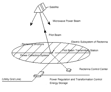
Figure 3: SPS and microwave WPT power generation system
Battery System
The designed full-scale battery energy storage system (BESS) will be lithium-ion and will be capable of providing power to the habitat for the duration of the lunar night, be vacuum compatible, be able to withstand extreme lunar environments, be rechargeable via solar panels and wireless power transmission and most importantly will be lightweight to allow for feasible transportation and implementation on the moon.
The BESS will be a battery farm consisting of numerous battery banks made up of lithium-ion cell modules. The system will be capable of providing 150 kWh constant power to the habitat for up to 52 hours which is the maximum duration of the lunar night.

Figure 4: Full-scale BESS system design
The battery management system (BMS) prototype for the IGLUNA field campaign was designed to represent a BMS that would be used in the full-scale system design. This is achieved by incorporating solar panel charge capability and relevant safety elements such as cell balancing as shown by the circuit diagram.

Figure 5: BMS IGLUNA field campaign prototype diagram
A 3 series 2 parallel lithium-ion cell module will be assembled and be monitored using an Arduino Uno and corresponding circuitry to ensure sufficient cell and circuitry protective elements and accurate voltage and current measurements.
Fuel Cells
A fuel cell is a device that converts chemical potential energy, stored in molecular bonds, into electrical energy and in the form of a PEM the fuel cell uses hydrogen and oxygen gas as fuel. There are many different forms of fuel cell; some requiring hydrogen and others requiring carbon dioxide with after power generation the by-product is water. Due to the goal of the investigation to utilise the water in the form of ice already present at the Shackleton Crater as a fuel the focus will be on the hydrogen fuel cell. Hydrogen fuel cells are up to 60% efficient with today’s technologies but theoretical efficiency could be as high as 83%. The fuel cell consists of stacks which contain all the operations, and these can be combined to produce as much power as is needed. This generation capability, in addition to the high-power density and lightweight designs, make Hydrogen fuel cells a good candidate for space exploration. The presence of water on the moon which can be returned to hydrogen and oxygen through an electrolyser is the main advantage of the hydrogen fuel cell.

Figure 6: Hydrogen fuel cell developed CAD model
Thermal Mass
The system proposed and analysed is a solar-powered thermal energy storage system, employing two lunar regolith blocks as the thermal mass. The HTTER (High-Temperature Thermal Energy Reservoir) acts as the absorber and LTTER (Low-Temperature Thermal Energy Reservoir) as a radiator. A schematic of the energy flow occurring through the system is shown in the figure below. The RCC (Reflector/Concentrator/Collector) concept involves a set of primary Fresnel reflectors directing sunlight to an absorber tube containing a heat transfer fluid.

Figure 7: Energy flow diagram throughout the thermal mass system
They are accompanied by a secondary set of reflectors to further increase the optical efficiency of the system. The fluid once heated, passes through a pumped fluid loop system to heat the HTTER during the day. The regolith block is covered by a few millimetres long layer of dust, helping to alleviate the effects of the drastic temperature swings. Thereafter, the fluid passes through a heat exchanger, converting helium to steam and thus powering the Stirling engine. The HTF then passes through the LTTER, condensing and starting the cycle all over again. During the night, the HTTER preserves the fluid at the operating temperature enabling it to power the engine. An example layout of the thermal mass storage system can be seen as follows.

Figure 8: Thermal mass system diagram
What comes next…
The team are currently hard at work preparing for our Readiness Review with the Swiss Space Centre, scheduled for mid-May. This review is to establish our preparedness and final deliverables for the Field Campaign. As a result of the ongoing COVID-19 pandemic, the Field Campaign is being transitioned to an online format. Whilst this, unfortunately, means the team won’t be travelling to Switzerland, it also affords the opportunity for us to reach a wider audience; with anyone able to attend the event virtually from around the globe. Follow our social media channels or visit the IGLUNA 2020 website to keep updated on the arrangement for the event, we’ll provide an update in our next article!
