Introduction to Potentiometer Adjustable Voltage Divider
Follow article
 Dave from DesignSpark
How do you feel about this article? Help us to provide better content for you.
Dave from DesignSpark
Thank you! Your feedback has been received.
Dave from DesignSpark
There was a problem submitting your feedback, please try again later.
Dave from DesignSpark
What do you think of this article?
Introduction
A potentiometer is a three-terminal resistor with a sliding or rotating contact. It is an adjustable voltage divider with two static contacts and one moving contact. The moving terminal is a wiper that travels across the resistance element, usually in an arc controlled by a rotary knob. Rotating the knob gives a ratiometric division of the potential across the resistance element. Potentiometer generally used in speakers and receivers for volume control. In addition, it cannot directly control the motor because its power is too small.
1 Potentiometer Wiring
The potentiometer can be used as a three-terminal component or a two-terminal component. The latter can be regarded as a rheostat. For a general potentiometer (three pins), the slider near the centre which is a resistance wire. The two pins at both ends of the resistance wire are connected to the input and the ground (some are not connected), respectively. That is, one pin is connected to the input signal and the other pin is grounded. At this time, the resistance wire has a total resistance value on the two sections. You move the sliding piece to go across this resistance wire to get a variable resistance. If the input and output signals are reversed, the sliding direction of the slide is opposite to the resistance change.
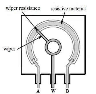
Figure 1. Potentiometer Structure
1) For a potentiometer (or a trimming resistors) with traditional pins (three pins), the resistance at both ends is fixed, and the resistance of the middle pin is variable. That is, the terminal on both sides of the potentiometer is total resistance, and the middle is changing. For example, the power supply is connected from any one contact on resistor sides and output from the middle contact, and the voltage changes with the rotation of the middle contact.
2) Although the resistance can vary with the slider, the total resistance value of pins is fixed. At this time, the potentiometer is equal to a current controller, and the selected current output terminals must be the sliding terminal.

Figure 2. Potentiometer as Voltage Divider
3) If a potentiometer used as a variable voltage divider, one contact connects to the input voltage, the middle contact connects to the output voltage, and the other contact can be grounded. When the rotary handle or sliding handle of the potentiometer take action, the movable contact slides on the resistor. At this time, an output voltage that has a certain relationship with the external voltage, wiper angle and travel stroke.
4) If a potentiometer used as a variable resistor, one end connects to the input voltage, the middle-end connects to the output, and the other end can be suspended or connected to the middle-end to obtain a smooth and continuously changing resistance value.
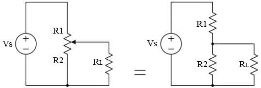
Figure 3. Potentiometer Circuit
2 Voltage Divider Potentiometer Basics
1. The resistor of the potentiometer is mostly made of polycarbonate synthetic resin. The following items should be avoided: ammonia, other amines, aqueous alkali solutions, aromatic hydrocarbons, ketones, lipid hydrocarbons, strong chemicals (excessive pH), etc., otherwise, it will affect potentiometer performance.
2. When soldering the potentiometer terminals, avoid using water-capacitive flux, which will cause metal oxidation and mould material. Using inferior flux, poor soldering may cause problems in soldering, resulting in poor contact or open circuit.
3. If the soldering temperature of the terminal is too high or the soldering time is too long, it may cause damage to the potentiometer. The temperature range of the plug-in potentiometer is 235℃±5℃; the wire bonding type is 350℃±10℃, and the soldering point should be more than 1.5mm away from the potentiometer body. In addition, avoid heavy pressure on the terminals, otherwise, it is easy to cause poor contact.
4. During soldering, the height of the flux entering the printing machine board should be adjusted properly, and it should be avoided to affect the potentiometer. Because it will cause poor contact between the brush and the resistor, or result in noise.
5. The potentiometer is better in the voltage adjustment structure.
6. Avoid condensation or water droplets on the surface of the potentiometer, and avoid using the potentiometer in a humid place to prevent insulation deterioration or short circuit.
7. When fixing the screws of the rotary potentiometer, the strength should not be too strong to avoid poor rotation. For the direct-sliding potentiometer, avoid using long screws, otherwise, it may hinder the movement of the sliding handle and even damage the potentiometer itself.
8. In the process of putting the potentiometer on the knob, the pushing force should not be too large (don’t exceed the parameter index of the rated pushing and pulling force), otherwise it may cause damage to the potentiometer.
9. The rotary force of the potentiometer will decrease as the temperature increases, and become smaller as the temperature decreases. If the potentiometer is used in a low-temperature environment, it needs special low-temperature resistant grease.
10. If the shaft or sliding handle of the potentiometer is too long, it is easy to shake and cause the instability of the circuit signal.
11. The carbon film of the potentiometer can withstand the ambient temperature of 70℃, and its function may be lost when the temperature is higher than 70℃.
12. For an adjustable potentiometer, when the DC is allowed to pass through the movable contact, the problem of anodic oxidation may occur. In this case, it is best to connect the component with the negative end and connect the moving contact with the positive end.
13. The load current of the adjustable potentiometer cannot be increased. For actual current measurement put an ammeter in series with the potentiometer in the active circuit.
14. Do not exceed the rated power when using the adjustable potentiometer. For example, when the power dissipation exceeds the rated value, it will cause the potentiometer to overheat.
15. A Potentiometer is sensitive, it is capable of measuring very small potential differences, and shows a significant change in balancing length for a small change in potential difference being measured.
16. A DC potentiometer is created by dropping voltage across a set of resistors in series. Different resistors will produce different values. In AC potentiometer, one can use resistors or even inductors or capacitors as impedances which will drop voltages and provide a voltage less than the applied voltage.
17. If positioned the potentiometer wiper on the centre of the resistor element then the voltage at the wiper is 50%; if the wiper is positioned 1/4 of the way from the negative node then the wiper voltage is 1/4th the entire voltage.
18. Potentiometer nomenclature: It generally use the direct marking method. Letters and numbers are marked on the potentiometer shell to indicate their model, nominal power, resistance, and the relationship between resistance and rotation angle.

3 Potentiometer Measures
The main checking requirements for the potentiometer are:
- The resistance value meets the circuit requirements.
- The connection between the centre sliding end and the resistor is good, and the rotation is smooth. For potentiometer with switches, the switch action should be accurate, reliable and flexible.
Therefore, the performance of the potentiometer must be checked before use.
1) Resistance measurement: First, select the appropriate gear of the multimeter according to the resistance of the measured potentiometer. Whether the resistance between the two ends of the AC is consistent with the nominal resistance. Rotate the sliding contact, and its value should be fixed. If the resistance indicates infinite, the potentiometer is damaged.
2) Then measure the contact between the centre end and the resistor, that is, the resistance between the two ends of BC. The method is to set the ohm range of the multimeter in the appropriate range. During the measurement, slowly rotate the shaft and observe the reading of the multimeter. Normally, the reading changes steadily in one direction. If there is a jump, drop, or blockage, it means that the movable contact has failures.
3) When the centre end slides to the head or the end, the resistance value of the centre end and the coincident end is 0 for an ideal state. In the actual measurement, there will be a certain value (generally determined by the nominal value, generally less than 5Ω), which is normal.
Get more info from Potentiometer - A Three-Terminal Resistor.