Pandemic Surveillance System
Follow project Dave from DesignSpark
How do you feel about this article? Help us to provide better content for you.
Dave from DesignSpark
Thank you! Your feedback has been received.
Dave from DesignSpark
There was a problem submitting your feedback, please try again later.
Dave from DesignSpark
What do you think of this article?
 The main purpose of this project is to design a system in which the number of persons entering or leaving the store is tracked and detect their temperature. Then, displayed on the screen (LCD).
Pandemic Surveillance System
This project describes the design and work of a Pandemic Surveillance System. The main purpose is to design a system in which the number of persons entering or leaving the store is tracked and displayed on the screen (LCD). When someone enters the store, the count would be increased and the buzzer will sound, whereas on leaving, the count would decrease and the buzzer will sound too. PIR sensing mechanism is used to sense the presence of visitors and the entire counting operation is completed by Arduino. Next, the vibration motor is used to inform the users by vibrating on receiving signals. Based on our project, when a user or customer passes through the door, the vibration motor will vibrate and this shown to indicate that someone is entering the store. The next component used in this project is a temperature sensor. Temperature sensor functions as an electronic device that measures the temperature of environments and converts the input data into electronic data in order to record monitor or signal temperature changes. In our project, the temperature sensor is used to detect the temperature of visitors entering the store while the buzzer will sound to indicate the level of temperature of the visitor. For example, when the temperature of visitors is too low and too high, all the led will be light up, all the buzzers will sound and it is stated as a none valid temperature. Next, when the temperature is good, the green led will be light up and the buzzer will sound, when it is moderate, the yellow led will be light up same goes as the buzzer, and lastly, when the temperature is high, the red led will be light up and the buzzer will sound. Lastly, the current visitor and the temperature result will show on LCD.
1.1 Temperature Measurement
Table 1.1
|
TEMPERATURE (0C) |
LED LIGHT |
| < 35 |
Green, Yellow, Red - Not Valid - |
| 35 - 37 | Green |
| 38 - 39 | Yellow |
| 40 - 43 | Red |
| > 43 |
Green, Yellow, Red - Not Valid - |
2.0 Circuit Diagram
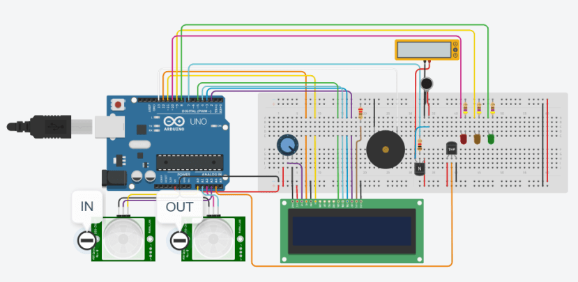
Diagram 2.0: Full circuit
3.0 The Diagram of Simulated Project
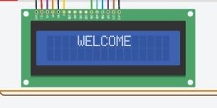
Diagram 3.1
Start simulation.

Diagram 3.2
The LCD display number of visitors.

Diagram 3.3
The LCD display temperature of visitors.

Diagram 3.4
The PIR sensor sensing visitors, piezo will sound.

Diagram 3.5
The Vibration Motor will vibrate.

Diagram 3.6
The temperature sensor works.
When temperature < 35, all LED lights up and piezo will sound.

Diagram 3.7
The temperature sensor works.
When temperature >= 35, LED green lights up and piezo will sound.
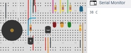
Diagram 3.8
The temperature sensor works.
When temperature >=38, LED yellow lights up and piezo will sound.

Diagram 3.9
The temperature sensor works.
When temperature <= 42, LED red lights up and piezo will sound.

Diagram 3.10
The temperature sensor works.
When temperature <= 46, all LED lights up, and piezo will sound.

Diagram 3.11
People in, visitor count 1.
LCD displays total visitors and “PLEASE VISIT”.

Diagram 3.12
After that, the LCD displays the temperature of
the visitor.

Diagram 3.13
People out, visitor -1.
LCD display.

Diagram 3.14
When people out, the LCD display temperature of the current visitor.

Diagram 3.15
LCD display “PLEASE WAIT”
If total visitor =10 and buzzer will sound until
the number of visitors = 9.
4.0 Tinkercad URL Link of Design Project