Learning Mikroe Clicker 2 - Project 2: Automate your Home
Follow project
 Dave from DesignSpark
How do you feel about this article? Help us to provide better content for you.
Dave from DesignSpark
Thank you! Your feedback has been received.
Dave from DesignSpark
There was a problem submitting your feedback, please try again later.
Dave from DesignSpark
What do you think of this article?
 In the second project of our Learning Mikroe Clicker 2 series get to grips with the Motion, Relay, Buzz and UART Click modules as you learn how to build a basic home automation application.
Parts list
| Qty | Product | Part number | |
|---|---|---|---|
| 1 | MikroElektronika Clicker 2 for STM32 MIKROE-1685 | 8829048 | |
| 1 | MikroElektronika USB UART Click USB to UART Add On Board, FT232RL - MIKROE-1203 | 8828913 | |
| 1 | MikroElektronika Relay Click - MIKROE-1370 | 8209858 | |
| 1 | MikroElektronika BUZZ Click Buzzer Add On Board - MIKROE-945 | 9235961 | |
| 1 | MikroElektronika Motion Click - PIR500BMotion Sensor Add On Board - MIKROE-1589 | 8829008 | |
| 1 | MikroElektronika mikroBUS expansion shield - MIKROE-1154 | 7916485 | |
Welcome to Automate your Home with MikroElektronika Clicker 2 for STM32. This is the second project in our learning with MikroElektronika series - from beginner to advanced - these projects will help you get started with embedded development for the first time, or if you are an experienced engineer, to familiarise yourself with the Mikroe development environment.
You will learn:
- Necto studio development environment
- Writing a microSDK application in Embedded C
- Integrating external libraries into your application
- Extending the capabilities of your Clicker 2 with add-on Click modules
In this series:
- Project 1- Getting Started with MikroElektronika Clicker 2
- Project 2 - Automate your home
- Project 3 - Build and connect an IoT weather station to the cloud
Home Automation Index
Part 0: Preparation
Part 1: Building a basic home automation device
Part 2: Extending the project
Part 0: Preparation
0.1 Download and Install NectoStudio
First, ensure you have downloaded and installed NectoStudio, the MikroElektronika cross-platform IDE. A free 90-day trial is available for evaluation to allow you to get started.
0.2 Hardware
To complete this project you will require a MikroElektronika Clicker 2 for STM32, the mikroBUS shield as well as four MikroE 'Clicks' which are an easy way to add additional functionality to the Clicker 2.
- Clicker 2 for STM32 - MIKROE-1685
- MikroBUS shield - MIKROE-1154
- Motion Click - MIKROE-1589
- USB UART Click - MIKROE-1203 - provides a UART interface via a Micro USB connection. This will allow you to communicate between the Clicker 2 and your PC/Mac
- Relay Click - MIKROE-1370
- Buzz Click - MIKROE-945
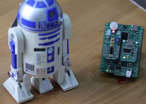
0.3 Assembling the Hardware
- First, we need to assemble the Home Automation device, we’ll start by inserting Motion Click to mikroBUS1 and USB UART Click to mikroBUS 2 socket on the Clicker 2 development board.

- On the MikroBUS Shield – we will insert Relay Click on mikroBUS 1 and Buzz Click on mikroBUS 2 socket. Then, connect the MikroBUS Shield to the Clicker 2 development board.

Part 1: Building the motion detector
1.1 Setting up NectoStudio Project
After installing the NectoStudio and registering for your trial license, we need to open NectoStudio and setup the project.
- Click on New Project.
- Enter the project name and choose where the project will be saved.
- Select the appropriate project template - for this example, we will choose the following settings:
- language - mikroC
- template - mikroSDK Application
- project type – Application

- Select an appropriate profile – for now, Clicker 2 for STM32 doesn’t have its own hardware profile in NectoStudio, but that will be added in future updates. For now, we can use any Fusion for ARM / STM32 v8 profile, because they are based on the STM32F407 MCUlect the Fusion for ARM v8 profile and then click on Next and in the next window on Finish.

Upon creating the new project, we will see the default template for creating the mikroSDK 2.0 programs.
1.2 Update Board Configuration File - board.h for MikroBUS shield
We will use both mikroBUS sockets for this example, so we need to change the board.h file and add the pins that are connected to mikroBUS 1 and 2 sockets.
- Navigate to board.h - y>ou can change this file in NectoStudiowhen the default template is displayed – in main.c file, on the line: #include “board.h” Right-click on board.h file and choose option Goto definition or F2 to open the board.h file in a new window.
- Comment the lines mikroBUS1, mikroBUS2,mikroBUS3 and mikroBUS 4 and copy the lines from the board.h we supplied with this project.
This change of the board.h use the pinout of the Clicker 2 development board on the mikroBUS sockets – both on Clicker 2 and MikroBUS Shield.


1.3 Download and configure libraries - Motion, Relay, Log
Before we can use the Temp&Hum 4 Click board, we need to download the library from the Packages menu.
- Download Libraries - Click on the Packages menu and click on Browse tab – enter the package name, when the library is displayed click on Install. After the library installs – it will be displayed in the Installed tab. From there you can access the various information such as library version, description of the most used functions and example of the code.
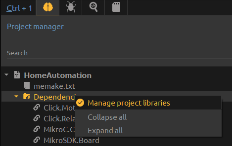
- Configuring Libraries - after you install the library, it will become an available option in the Dependencies tree in the Project Manager window. Access the library manager by right-clicking on Dependencies and selection option Manage project libraries, which will open the Library Manager.
- Select the required libraries Motion and Relay from Click group and Log from MikroSDK group, Click OK and wait for NectoStudio to reconfigure the project.

- There’s one library that’s still not included in NectoStudio – Sound library, but we will use the Legacy driver library. To include this library in the project – we first need to copy the Sound.h and Sound.emcl files to the root folder of the project. Then – in Project manager window, double click on the memake.txt file to open it and add the following lines :
binaries : {
sound.emcl
}

headers: {
sound.h
}- Save and close the file.
With the project's dependencies configured, now we can get to building the application.
1.4 Includes and context structures
- The first thing we need to do is ensure the header files for the libraries we require are included.
#include “board.h”
#include “log.h”
#include “motion.h”
#include “sound.h”
#include “relay.h”- Create context structure objects for motion, relay and logger and two more for motion detection state. The code should look like the following :
static motion_t motion;
static relay_t relay;
static log_t logger;
motion_detect_state_t motion_state;
motion_detect_state_t motion_old_state;
1.5 Initialise drivers
- Within the application_init() function in main.c, we need to initialize the driver objects and map the drivers to the pins on which the Click modules are connected.
In the Application Init section of the code – we will configure the Click Boards by initializing them to appropriate mikroBUS socket and assigning the default configuration values.
Log will use PD9 and PD8 pins, these pins correspond to the pins on the UART pins on the mikroBUS 2 socket of the Clicker 2 – we will define them with log_cfg.rx/tx_pin.
Motion Click will be configured on mikroBUS socket 1.
Relay Click is on mikroBUS 3 socket ( which is mikroBUS socket 1 on the MikroBUS Shield, but in the board.h is defined as mikroBUS 3 )
Buzz Click uses the B8 pin from mikroBUS 4 socket ( mikroBUS 2 on Shield ).
We will use the SoundInit function to configure the B8 pin.
The Application Init section should look like this::
  log_cfg_t log_cfg;
  motion_cfg_t cfg;
  relay_cfg_t cfg_r;

  // Log initialization
  // Starts with 2 second delay

  Delay_ms( 2000 );

  log_cfg.level = LOG_LEVEL_DEBUG;
  log_cfg.rx_pin = PD9;
  log_cfg.tx_pin = PD8;
  LOG_MAP_USB_UART( log_cfg );
  log_init( &logger, &log_cfg );
  log_printf( &logger, "Application Init\r\n");
  Delay_ms( 300 );

  // Motion Click initialization and config

  motion_cfg_setup( &cfg );
  MOTION_MAP_MIKROBUS( cfg, MIKROBUS_1 );
  motion_init( &motion, &cfg );
  log_printf( &logger, "Motion Click initialized!\r\n");
  Delay_ms( 300 );
  motion_default_cfg( &motion );
  log_printf( &logger, "Motion sensor enabled!\r\n");
  Delay_ms( 300 );

  // Relay Click initialization and config

  relay_cfg_setup( &cfg_r );
  RELAY_MAP_MIKROBUS( cfg_r, MIKROBUS_3 );
  relay_init( &relay, &cfg_r );
  log_printf(&logger, "Relay Click initialized\r\n");
  relay_default_cfg( &relay );
  Delay_ms( 500 );

  motion_state = MOTION_NO_DETECT;
  motion_old_state = MOTION_DETECTED;

  // Sound init

  Sound_Init(&GPIOB_ODR, 8);
  Delay_ms( 1000 );
  buzz_play(1000, 65);
  Delay_ms( 300 );
  buzz_play(1000, 65);
  Delay_ms( 300 );
  buzz_play(1000, 65);
  Delay_ms( 300 );
1.6 Write the application
Finally, we need to add our application code within application_task(), this code is run and looped continuously after application_init() has been run.
In the Application Task, we will check the motion state and for every change assign appropriate action.
If the new movement is detected, we will display the message in PC terminal, play the Tone on the Buzz Click and turn ON the Relay Click.
void application_task()
{
  // Task implementation
  motion_state = motion_get_detected( &motion );

  if( motion_state == MOTION_DETECTED && motion_old_state == MOTION_NO_DETECT )
  {
    log_printf( &logger, "Movement detected\r\n");
    motion_old_state = MOTION_DETECTED;
    buzz_play( 1000, 65 );
    relay_set_state( &relay, 1, RELAY_STATE_ON );
    log_printf( &logger, "Relay turned on!\r\n");
  }

  if( motion_old_state == MOTION_DETECTED & motion_state == MOTION_NO_DETECT )
  {
    log_printf( &logger, "Standby\r\n");
    motion_old_state = MOTION_NO_DETECT;
    relay_set_state( &relay, 1, RELAY_STATE_OFF );
    log_printf( &logger, "Relay is off!\r\n");
  }
}
Your code is now complete!
1.7 Configuring the clock
Next, we must configure the timing source for the STM32 microcontroller on the Clicker 2 - this is often referred to as the clock.
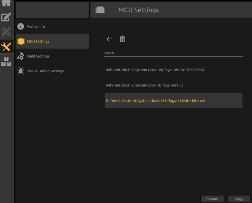
- Navigate to MCU settings - Click on the
icon, choose MCU Settings and click on the Load configuration from scheme template.

- Load the appropriate clock configuration scheme - Select: >Referent Clock : 16; System clock:168; Tags: 168MHz internal and press Apply.
1.8 Building the application
We now need to build the code - i.e turn the code into a binary file which is understood by the STM32 microcontroller.
- Click the Hammer icon in the main menu bar to start building your project.

If the project doesn’t have any errors in code, it will build successfully and upon completing the build it will display the following message:

1.9 Programming Clicker 2
Finally, we will program the application onto the Clicker 2 development board through the bootloader – here’s how I do it.
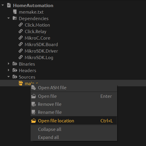
- Right-click on the main.c file in the Project Manager window and choose Open file location.
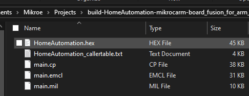
- Go one folder above and find the build-HomeAutomation folder

- In the HomeAutomation folder, you’ll find the HomeAutomation.hex file, which we’ll program
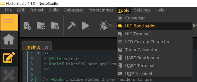
- Now let’s open the HID bootloader from Tools menu
- Connect the USB cable to the development board and turn the Clicker 2 ON.
You’ll see the name of the development board and in the next 5 seconds, it will be connected to the bootloader. Press Reset on the dev board to connect it again if needed.
- Drag the HomeAutomation.hex file to the HID Bootloader and you will initialize programming.


After the programming finishes and board restarts, after 5 seconds the board will turn on.
In next couple of seconds, you’ll hear 3 tones that signalize that board is initialized successfully.
1.95 Testing the application
When you connect the USB cable to USB UART Click – you can connect to the appropriate COM port in UART terminal and check the status of the Relay click.
- Connect an additional cable to the USB UART Click and open the UART Bootloader.
- Select the appropriate COM port and enter the baud rate chosen earlier - 9600bps.
If you have been successful the output on the terminal should look like this:
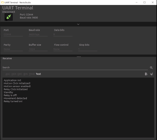
After movement is detected – the Relay Click will turn on Relay 1. You can connect the terminal connectors to a simple circuit ( let’s say – a light source or led blink circuit ) and switch it ON/OFF each time movement is detected.
Part 2: Extending the Project
Now that you have successfully built our example project - get creative! Take a look around you and see how you can put your new skills to use with your own project - perhaps you could build a motion-activated battery-powered night light, an automatic hand sanitiser dispenser or a pet food dispenser that dispenses only when your pet is near and at the correct time of day.
Share your project with us on Designspark when it is completed!