Making a simple AM Radio
Follow article
 Dave from DesignSpark
How do you feel about this article? Help us to provide better content for you.
Dave from DesignSpark
Thank you! Your feedback has been received.
Dave from DesignSpark
There was a problem submitting your feedback, please try again later.
Dave from DesignSpark
What do you think of this article?

First experiences with radio frequency circuits.
All the other projects I have made so far have been digital and microcontroller based, with the one exception to this being the Nutclough amplifier, which was assembled from a kit. The big difference in this project is that unlike the other ones which I have built from scratch it is an analogue RF circuit.
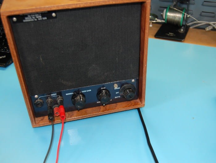
We already had some TA7642 AM receiver ICs in the workshop and some PP3 battery clips to hand, so I wanted to use both of these components in my circuit. Since I had never built any analogue circuits before I wanted to keep this fairly simple so would use an external test audio amplifier for testing.
After doing a bit of research it became apparent that a very important part of the radio is a tuned circuit, which can be tuned to a particular frequency in order to select the radio station desired. This can be made from an inductor and a variable capacitor connected in series or parallel.
I began looking for examples of circuits for the TA7642 and the majority used either a 1.5v or 3v supply. I occasionally found ones which used a 9v battery, however most of these seemed to incorporate built in amplifiers. After a bit more searching I finally found one which did not.
This circuit consists of:
- 1 x 9v battery
- 1 x 10k resistor
- 1 x 1k resistor
- 1 x 100k resistor
- 2 x 1n4148 diode
- 1 x .01uf capacitor
- 1 x .1uf capacitor
- 1 x 470uf+ capacitor
- 1 x 1uf+ capacitor
- 1 x TA7642 IC
- 1 x ferrite coil antenna
- 1 x variable capacitor
- 1 x test amplifier
- 1 x switch
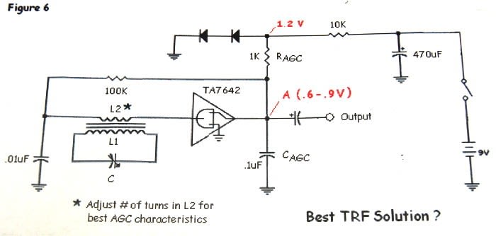

I decided not to include a switch, as I could just remove the battery, so I removed the switch from the schematic. The ferrite coil antenna which I had had both a long wave and a medium wave coil on separate formers on the ferrite rod, each coil consisted of a longer coil and a shorter coil too. So there were four coils in total.
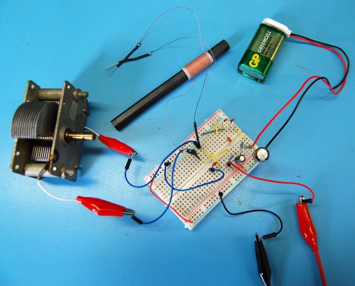
I began connecting the components as above in the schematic, using a breadboard. When I powered up the circuit I could hear a muffled radio station, but when I adjusted the capacitor nothing changed and it should have done.
I checked the layout against the schematic again and then powered up the circuit to find the same result. I then checked the values of all the resistors and capacitors for errors, here I found I had accidentally used a 100 ohm resistor instead of 100k. I replaced this and powered up the circuit once more hoping this would resolve the problem, but again it didn't.
When I initially began looking at tuned circuits many of them only used a single coil of one length. So I then wound my own ferrite antenna using enamel wire and I attempted wiring my circuit with this.
The circuit didn't work with this coil, so I tried again using the original medium wave coil, but this time not using the shorter winding. Instead by connecting the longer winding and variable capacitor in parallel and directly in circuit.


When the circuit was powered up this time it surprisingly worked! Varying the capacitance tuned the circuit and the radio was now quite clear to listen to.
I'm still unsure as to why the radio circuit didn't work the first time and I will look into this further to try understand what went wrong.

Another fun project as I learn more about electronics!