LASER-SHOOTING ROBOT- nerds’ enemies beware!
Follow article Dave from DesignSpark
How do you feel about this article? Help us to provide better content for you.
Dave from DesignSpark
Thank you! Your feedback has been received.
Dave from DesignSpark
There was a problem submitting your feedback, please try again later.
Dave from DesignSpark
What do you think of this article?
If you were expecting a sci-fi weapon from the title, I’m sorry; but you will be disappointed with this article. However, if you are into electronics you may find it interesting.
The purpose of this project was to build something similar to an infrared shooting arcade. Although the aim has been fulfilled, there’s still room for improvement. If you start from here you could make something even funnier.
The project is based on microcontroller PIC16F877A and consists of a structure of 2 servomotors whose positions are controlled using a joystick. On top of them there is a laser that is activated by pressing the joystick’s switch. There is also a general switch that serves to switch all the circuit on or off.
PCB Design and components
The PCB has been designed with DesignSpark PCB 8.0 and the schematic and PCB files are attached at the end of this article. It is a Single Layer Board (tracks only on bottom side) with copper pour areas on both sides (5 V on top side and Ground on bottom side). Its area is 55 x 70 mm.
The components used in this project are:
- SPDT switch
- 9 V transformer with connector (*)
- Switching regulator with 5 V outp
ut
- Microcontroller PIC16F877A
- 4 MHz Oscillator (for the μC)
- 2 servomotors SG90 fixed in a structure whose original use was to hold a webcam
- Laser
- Resistors with various values
- Capacitors with various values and functions (bulk capacitors, decoupling capacitors)
- Several Pin Headers and cables
(*) Note about the power supply: it was initially thought to use a 9 V battery as power supply. Nevertheless, the current requested by the servomotors (around 120 mA each) when they move causes a significant drop in the power supply output voltage. As a result, a brown-out reset happens and the servomotors return to the reset position. This problem took place every time one servomotor moved and it wasn’t admissible.
Although different solutions were tried (bigger bulk capacitors for the servomotors, switching the microcontroller’s brown-out reset bit off), in the end it was decided to change the power supply.
Source code and operation
The source code is attached at the end of this article. It has been written in C using MPLAB® IDE v8.89 and HI-TECH ANSI C Compiler. The current code only uses 5.5% of PIC16F877A’s program memory and 4.6% of its data space.
Before designing the PCB, the code has been verified using PICDEM 2 PLUS Demo Board with the debugger MPLAB® ICD 3.
The laser-shooting robot operation is explained below. It is far easier that it may seem at first sight.
1. Servomotors
The servomotors 
The first servomotor controls roll (φ, turn around the Z axis) while the second controls yaw (ψ, turn around the X axis).
The PWM (Pulse Width Modulation) control signal must have a 20 ms period (50 Hz frequency) and a Duty Cycle between 1 and 2 ms so the servomotor can cover a 180º range.
These signals are generated using the Compare Mode of each of the 2 CCP (Capture, Compare and PWM) modules that PIC16F877A has.
Although the servomotors’ control isn’t quite difficult, some details must be taken into account to grasp full control of them.
- Servomotors’ real operation: servomotors’ operation in real life differs from ideal operation (not really surprising). If the PWM terminal is fed with a 50 Hz signal with Duty Cycle between 1 ms and 2 ms, in most cases the “shooting range” will be far from 180º.
If you want to achiev
For instance, in this project, one of the servomotors uses a Duty Cycle between 0.6 ms and 2.4 ms, while the other servomotor has a Duty Cycle between 0.7 ms and 2.4 ms. Obviously, each servomotor’s tolerances will cause the proper range for the Duty Cycle range to be slightly different.
- Servomotors’ limits: once you have “gauged” the servomotors, I suggest you to limit the servomotors’ movements by software. For example, when the first servomotor (that controls roll) reaches Duty Cycle = 0.6 ms, which corresponds approximately to the extreme right position, all orders from the user to turn right should be ignored. This way we can assure the servomotor won’t be forced beyond its limits.
- Servomotors’ position feedback: in fact, no real feedback is used, but we must assure each servomotor reaches the desired position. This means that the PWM with the corresponding Duty Cycle has to be continuously sent to the servomotor, even if there are no changes in its position.
This way, if the servomotor is externally forced (not using the joystick, action not advised as it can damage the servomotor) to move to another position, as the PWM signal is continuously feeding the servomotor, it will return immediately afterwards to the previous position.
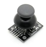
2. Joystick
The joystick counts with 5 terminals:
- GND, +5V
- VRx, VRy: they provide an analog signal between 0 V and 5 V proportional to the joystick’s position in axis X and axis Y respectively. These voltages are converted in a number between 0 and 1023 using the microcontroller’s 10-bit ADC (Analog-to-Digital Converter).
- Switch: it is the output terminal for the joystick’s pushbutton and requires a pull-up resistor. When it is pressed, the laser on top of the servomotors is activated.
3. Interaction between servomotors and joystick
φ (turn around the Z axis) and ψ (turn around the X axis) of the robot can go approximately from -90º to +90º. This range has been divided for both angles in 11 positions, numbered from 0 to 10, so there’s a gap of around 18º between 2 consecutive positions.
Position number 10 corresponds to the lowest Duty Cycle (0.6 ms and 0.7 ms respectively for the servomotors used in this project) and position number 0 corresponds to the highest Duty Cycle (2.4 ms for both servomotors in this case). Obviously, the Duty Cycle for positions from 1 to 9 for each servomotor comes from dividing the corresponding Duty Cycle range in proportional segments.
Position 5 (0º) is the reset position and each time the circuit is switched on both servomotors return to this position, no matter which was the ending position the last time the circuit was switched off.
The relationship between the servomotors’ angular positions and the joystick are the following:
Joystick X position controls roll (angle φ, turn around the Z axis)
- Result CAD: 0 → -2 positions for φ (big turn to the left)
- Result CAD: 1-399 → -1 position for φ (small turn to the left)
- Result CAD: 400-600 → NO change in φ
- Result CAD: 601-1022 → +1 position for φ (small turn to the right)
- Result CAD: 1023 → +2 positions for φ (big turn to the right)
Joystick Y position controls yaw (angle ψ, turn around the X axis)
- Result CAD: 0 → -2 positions for ψ (big turn downwards)
- Result CAD: 1-399 → -1 position for ψ (small turn downwards)
- Result CAD: 400-600 → NO change in ψ
- Result CAD: 601-1022 → +1 position for ψ (small turn upwards)
- Result CAD: 1023 → +2 positions for ψ (big turn upwards)
Both angles can be modified at the same time but remember that when the robot reaches one of the extreme positions it will ignore the joystick’s orders until the movement direction changes. The picture below tries to reflect the robot’s operation explained above.

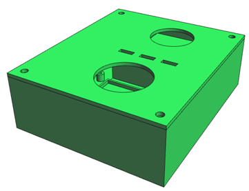
3D Design
The 3D design has been done with DesignSpark Mechanical 2.0 and the 3D files are attached at the end of this article. The design has 4 major parts: box, cover, robot support and joystick support.
- Box design: it has 4 small inner columns to hold the PCB (M2 or smaller screws should be used) and 4 large outer columns to fix the cover (M4 screws are suggested in this case). The transformer is fitted in a hole located next to one of the corners.
The box also has a compartment for the battery, although finally the power supply has been changed and this compartment is no longer needed. It has been left in case someone manages to use a battery as power supply.
- Cover design: it has 2 big circular holes, one at the back for the joystick and other at the front for the robot’s base; and 4 small holes for the servomotors cables, the laser’s cables and the switch. The hole for the joystick must be large enough to allow its free movement.
- Supports: there is one support for the robot and another for the joystick. Regarding the assembly, the cover’s bottom side has projections that fit into the supports’ holes.
It is highly recommended to view the assembly model. The visualization of each of the pieces that are part of the assembly can be activated or deactivated separately (this option can be very useful).
Video
(*) Attached files
- Source code (attachment 1): it must be included as a Source File in a MPLAB® Project. PIC16F877A must be the selected device. In other case, configuration settings will have to be changed.
- PCB files (attachments 2-4): schematic (2), PCB design (3) and 3D package library (4). (2) and (3) should be included in a DesignSpark PCB Project. (4) should be enabled using the Library Manager to visualize the PCB’s 3D View as it was intended.
- 3D design files (attachments 5-9): box (5), cover (6), servomotors support (7), joystick support (8) and 3D assembly model (9).