Incorporating a PanelPilotACE into the Red Tin Part One: A VU Meter with Envelope Follower Circuit
Follow articleHow do you feel about this article? Help us to provide better content for you.
Thank you! Your feedback has been received.
There was a problem submitting your feedback, please try again later.
What do you think of this article?

I was impressed with the PanelPilotACE after my first encounter and, as I mentioned in that blog, I started thinking about how I could use in The Red Tin. The thing that immediately sprang to mind was a VU Meter. The PanelPilot Design Studio comes with various templates for meters, although I had not seen anything for measuring sound levels.
Finding the right circuit
To convert the audio signal from the Red Tin into something the PanelPilot could usefully read I needed to build some kind of circuit. A web search threw up a number of suitable looking designs for unity gain amplifiers with the desired high impedance input — so that it doesn’t affect the sound quality — designed to drive conventional VU Meters. The Objective Sounds website was particularly informative and gave details of various different circuits.
A further search brought up a post on the Arduino Forum with a circuit for an Arduino VU meter envelope follower, which I thought could be just what I was looking for.
I ordered the components to try out 2 or 3 different circuits so I could see which worked best. I then tried a very “quick and dirty” passive circuit on breadboard that simply consisted of a 3.3k resistor, 4 diodes and a 100uF capacitor — but that didn’t produce the desired results and so I thought I would move straight on to the envelope follower.
VU meter envelope follower circuit
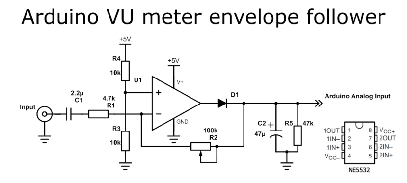
The blog post featuring this circuit gives a really clear description of what it is doing and so I will not go into detail here. Originally conceived as a circuit to drive an LED VU Meter powered by an Arduino, I was pretty sure I could use it with the PanelPilotACE to control a virtual meter, rather than LEDs via the analogue input on an Arduino.
These are the parts I used:
- 4.7k Resistor x 1 (707-7726)
- 10k Resistor x 2 (707-7745)
- 100k Resistor x 1 (707-7824)
- 47k Resistor x 1 (707-7805)
- Op Amp – NE5532 x 1 (081-0188)
- Diode – IN5711 (687-0763)
Circuit diagram from a post on the Arduino Forum by forum member PieterP. https://forum.arduino.cc/index.php?topic=492208.0
I had the circuit diagram and identified the pins on the op amp from its datasheet, so I was ready to go.
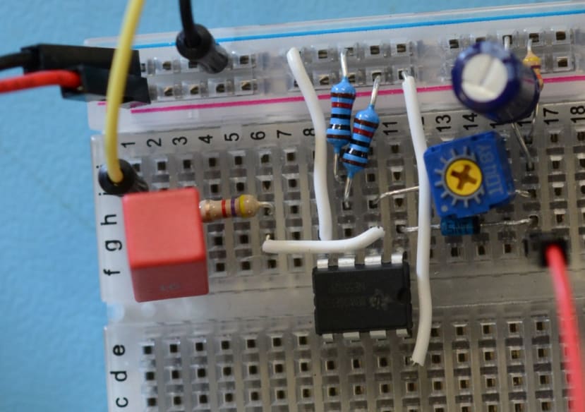
I made a version of the circuit on breadboard and measured the output voltage – with no input it hovered around 2.5V as expected. I connected an audio source to the input and could see it varying between 2.5V and just under 4V.
I used one of the dial templates in PanelPilot Design Studio and tweaked it to detect and display those voltages. So in the Analogue Input configuration, I set the Resolution with a minimum of 2.5V and a maximum of 4.5V. I then needed to set the Voltage Scaling in the Rotating Needle properties, with 2.5V mapping to 0 and 4.5V to 100. I also found that I could set the Angle range of the needle. In the template it was set at -90° for minimum, with +90° for maximum but if I varied these figures I could adjust the start and finish point of the needle to match my imported dial graphic.
Once the output from my circuit was connected to the analogue input on the back of the PanelPilot and a sound source connected, the needle on the dial bounced about just like a “real” VU meter.
I then made a much neater version and tried swapping out first the diode and then the Op Amp to see if that made any difference. I was only playing music from my PC through the circuit, so my results are not particularly accurate, but playing the same passage of music with the original NE5532 produced a wider response range than the TL072CP (030-4239) that I also tried. The different diodes did not make a discernible difference and so I left the last one that I used in place. For the record, I tried a IN5817 (625-4972) and a IN4001 (628-8931) , so if you were going to construct this circuit, either of those would do the job.
I also replaced the fixed resistor between pin 2 of the Op Amp and the output to the PanelPilot with a trimmer potentiometer (896-7138) which allowed me to tweak the output level.
I then edited the graphics in the PanelPilot template that I was using to give me something that would better suit the Red Tin with a choice of 3 different screens.
Next Steps
As far as the VU Meter goes I now need to build a stereo version of my circuit on strip board, so that it can be mounted in the tin, and then edit the PanelPilot display to reflect this.
Using the PanelPilotACE means I can change easily VU Meter style (as you can see in the video), which is great if you can’t decide if you prefer the bouncing needle or the LEDs. I could even switch between styles for different types of music. A big red warning light, if it is getting too loud, might be a good idea too (DJs are notorious amongst sound engineers for pushing all the levels into the red and damaging equipment as a result).
The ability to switch between screens means I can add other functions and a number of things come to mind – monitoring the voltage would be particularly useful when I was using the rechargeable 12V power supply. Monitoring and controlling the temperature around the UDOO x86 and sound card would also be useful, and a bank of buttons to control lights, smoke machine or even robot dancers might be a possibility.
I can envisage the PanelPilotACE becoming an integral and invaluable part of the Red Tin.


