DSPCB - Improve your schematic layout
Follow article
 Dave from DesignSpark
How do you feel about this article? Help us to provide better content for you.
Dave from DesignSpark
Thank you! Your feedback has been received.
Dave from DesignSpark
There was a problem submitting your feedback, please try again later.
Dave from DesignSpark
What do you think of this article?
Have you ever wanted to separately position the displayed symbol reference text and the component value to provide a neater schematic layout?
As an example separately place a component reference R15 from the value 1K.

This can be achieved by editing the component in the library and adding a second Reference which is then customised to display the value.
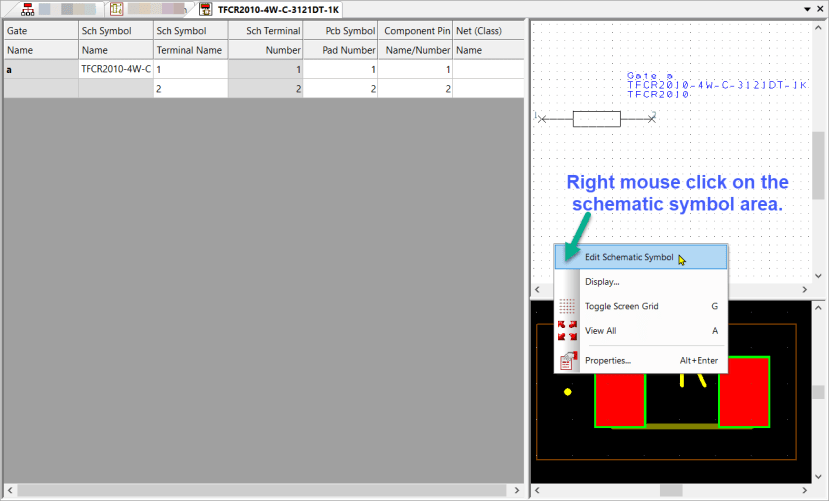
Launch the Library Manager, select the component to edit and then edit the schematic symbol.
Now we add a second schematic reference. From the Menubar select "Add" and then "Reference Origin".
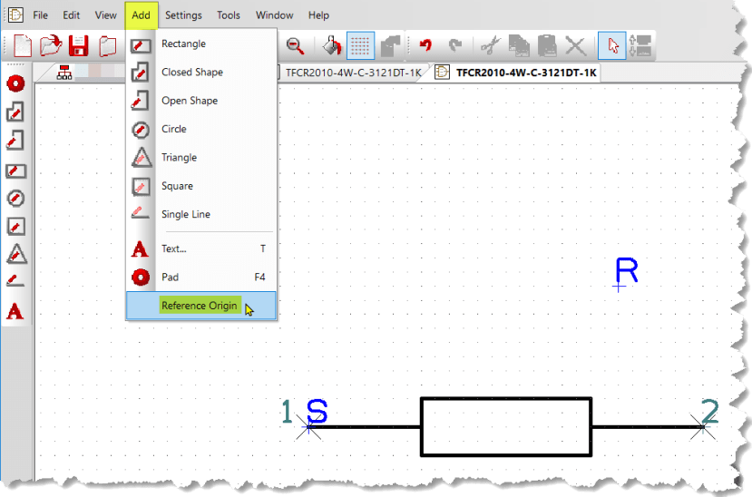
Click on the schematic to place.
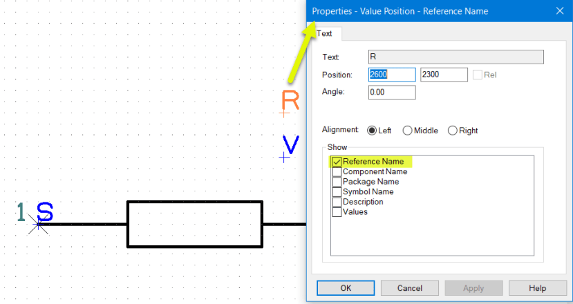
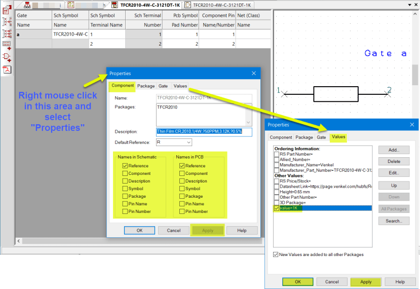
You are now ready to customise the reference, with the new reference origin selected, right-click and select "Properties". Deselect all the checkboxes under "Show" except for "Values".
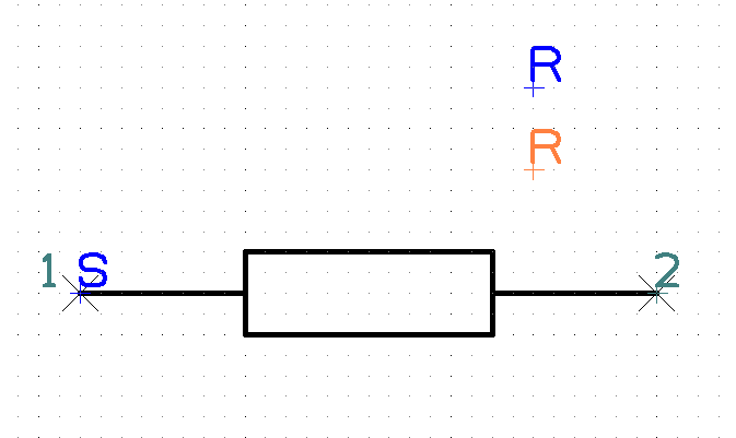
Click on <Apply> and the new Reference Origin will have the symbol "V" as shown.
Click <OK> to exit the window.

Next, select the original Reference Origin +R and check and configure the Properties as below.
Now "Save" the schematic symbol overwriting the current symbol in the library and then close the symbol edit window.
You are now back in the Component Editor window.
Here we perform some final configuration in the "Properties".
In the Component tab deselect everything you do not wish displayed and in the Values tab select the value you wish displayed.
Then "Save", overwriting the component in the library with the new symbol and settings.
You are now ready to use your newly configured component.
In your schematic design, when you "Add Component" and select this newly configured component you will be able to select and move the "Component Reference" and "Value" to any position you require.

This can be useful for schematic clarity or for allowing a higher density of components.

Important Note, if you have already placed the original component on your schematic sheet and then decide to make changes to the component in the library as described above, then when using "Update Components" the following checkboxes are suggested and require to be considered.
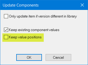
"Only update item if version different in the library", leave this 'un-checked' it will force the component to be reloaded from the library.
"Keep existing component values", if you have used the component but changed the local values in the schematic design, i.e. set to 2K, 4k7, or to any value different from the library component, always keep this box checked! If you do not all the existing values will be updated to match the original library component value.
"Keep value positions", If this is checked it will prevent the new reference positions you have created in the library component from populating the schematic sheet. The result is that the component reference and value will still be locked together and cannot be moved individually.
As a reminder, only one instance of a component from the library can exist in the design, so if you select one symbol and update "Selected Component", ALL instances of that component will be updated.
Schematic enhancement.
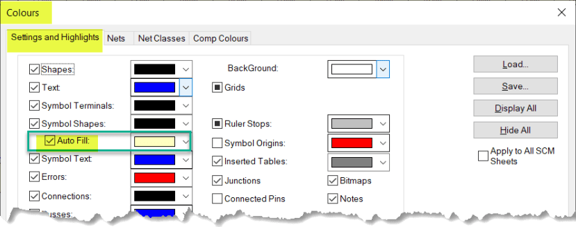
With an Engineer subscription, DSPCB allows a further simple visual enhancement is to apply a colour fill to the schematic symbol shapes. Note the shapes must be 'closed shapes'.
Launch the Colours window (shortcut C ) and check the following check box.
The schematic editor window will now change as shown below.
