Create a Soda Can Theremin
Follow article Dave from DesignSpark
How do you feel about this article? Help us to provide better content for you.
Dave from DesignSpark
Thank you! Your feedback has been received.
Dave from DesignSpark
There was a problem submitting your feedback, please try again later.
Dave from DesignSpark
What do you think of this article?
The theremin is an electronic musical instrument controlled without physical contact. The instrument's controlling section usually consists of two metal antennas that sense the relative position of the thereminist's hands and control oscillators' frequency with one hand and amplitude (volume) with the other. The electric signals from the theremin are amplified and sent to a loudspeaker. The sound of the instrument is often associated with eerie situations.
This project is going to demonstrate how to build a simple theremin using Digilent Electronics Explorer** Board and a soda can as the antenna! The theremin will only demonstrate pitch modulation. The block diagram shows the implementation.

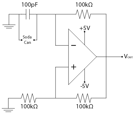
The antenna (the soda can) acts as one plate of a capacitor. Your hand will act as the other plate of the capacitor. Thus, by moving your hand nearer and further from the can, you are changing the capacitance of the circuit. This takes place within the variable-frequency oscillator portion of our circuit. As the capacitance in the oscillator changes, the oscillator's output frequency changes as well. This change in frequency can be heard at the speaker at the end of the circuit.
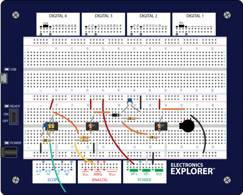
We will use the Digilent Electronics Explorer** to power the circuit. The Electronics Explorer** board includes all of the test and measurement equipment needed to design, build, and test analog and digital circuits of all types. Built around a large solderless breadboard, it includes a 4-channel mixed-signal USB oscilloscope, waveform generator, variable power supply, voltmeter, reference voltage generator, and thirty-two digital signals that can be configured as a logic analyzer, pattern generator, or anyone of several static digital I/O devices. All of these instruments can be connected to circuits built on the solderless breadboards using simple jumper wires.
Parts required for the Soda Can Theremin
- Digilent Electronics Explorer**
This item is no longer available, replacement model is Analog Discovery Studio.
- From Digilent Analog Parts Kit:
(184-0451)
- OP27 Operational Amplifier (x2) (709-5550)
- OP37 Operational Amplifier (522-8770)
- Small Speaker (188-2197)
- 100pF Ceramic Capacitor (831-2916)
- 0.047uF Ceramic Capacitor (906-0691)
- Small-signal Diode (1N3064)
- 10kΩ resistor (x2) (707-8300)
- 20kΩ resistor (x2) (125-1166)
- 47kΩ resistor (x2) (707-8369)
- 100kΩ resistor (x3) (707-8748)
- Breadboard pins
- Jumper Wires (189-2274)
- Soda can
- WaveForms Software
Build the Soda Can Theremin
The circuit will be built all on the breadboard of Electronics Explorer**. It is best to start towards one side of your breadboard and working towards the right to make sure it all fits.
Step 1 - Oscillators
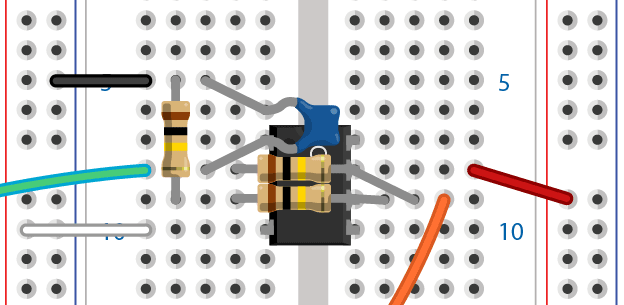
For the variable-frequency oscillator, we will be using the OP27 operational amplifier. Place the op-amp such that it straddles the valley of the breadboard and the notch is towards the top of the breadboard. Supply +5V and -5V to the op-amp. You also need to use a 100pF capacitor and three 100KΩ resistors. Programmable Power Supplies of Electronics Explorer** are used to supply power to the op-amp.

To save space on our breadboard, we will use the Electronics Explorer's** Arbitrary Waveform Generator to act as the fixed oscillator. Use WaveForms Software Application to apply a sinusoidal wave here. You want the sinusoidal wave to have a frequency close to that of the variable-frequency oscillator. In this project, that is about 25.5 kHz.

Step 2 - Weighted Summer
This next portion of the circuit, the weighted summer, mixes the signals from our fixed and variable-frequency oscillators. We will be using another OP27. Move a few holes down the breadboard from the oscillator and place the OP27 such that it straddles the valley of the board and the notched side is towards the top of the board. You also need to use two 47kΩ resistors and one 20kΩ resistor. The Arbitrary Waveforms Generator of the Electronics Explorer** acts as the power supply for the op-amp.


Step 3 - Envelope Detector
By mixing the oscillating signals with the weighted summer, a “beating” signal is produced. The new signal output from the weighted summer will be passed through an envelope detector which traces the beating pattern. The input of the envelope detector is the output of the weighted summer. You also need to use a diode, 0.47uF capacitor and a 10kΩ resistor. The orientation of the diode is very important. The diode in the Analog Parts kit is orange with a black band on one side. The side with the black band is “negative”.


Step 4 - Amplifier
The output signal of the envelope detector is actually ready to send to the speaker, but the result wouldn't be very loud. That being said, the final step before sending the signal to the speaker is an amplifier. The amplifier used here is an inverting amplifier built with an OP37 op-amp. The OP37 has an identical pinout compared to the OP27. It behaves similarly as well. You also need to use a 10kΩ resistor and a 20kΩ resistor.


Step 5 - Complete the whole circuit.
Connect the output of the amplifier to the positive pin of the speaker. Connect the speaker's other pin to one of the Electronics Explorer** ground rails. Attach a wire to the soda can and make sure there is metal-to-metal contact. The other end of this wire should be connected to a ground rail on the Electronics Explorer**. The green wire in the oscillator is held in your hand. Move your other hand around the soda can to play the theremin!
***NOTE: Digilent Electronic Explorer is End of Life. Replacement model is Analog Discovery Studio.

Analog Discovery Studio: A portable circuits laboratory
What is the Analog Discovery Studio?
The Analog Discovery Studio is a fully functional, portable test and measurement device that can turn any cross-functional space into a pop-up electronics laboratory. Equipped with 13 instruments, including an Oscilloscope, Logic Analyzer, Spectrum Analyzer, Waveform Generator, and more; the Analog Discovery Studio provides an entire stack of bench-top instruments with a convenient, replaceable, and breadboardable interface, perfect for enabling student learning anywhere.
Portable Design
The Analog Discovery Studio is designed to be a compact alternative to a stack of benchtop equipment. Its durable enclosure measures 1.25 x 9.25 x 7.5 inches and fits on a bench, desktop, or backpack. Students can access the Oscilloscope and Waveform Generators via breadboardable MTE cables, or industry standard BNC cables, and the Logic Analyzer, Pattern Generator, and Triggers can be accessed via MTE cables.
Circuits or designs can be built on the included, magnetically connected Breadboard Canvas and conveniently swapped out or removed for transit, making the transition from working in the lab to working at home as seamless as possible. The Breadboard Canvas also includes power supply outputs controlled by physical switches, common I/O built-in, and a large breadboardable surface. The Breadboard Canvas and the cost-optimized Blank Canvas can be purchased separately in the event that an extra is needed, or if the breadboards wear out.

