How can I place components on a PCB?
Follow tutorial
 Dave from DesignSpark
How do you feel about this tutorial? Help us to provide better content for you.
Dave from DesignSpark
Thank you! Your feedback has been received.
Dave from DesignSpark
There was a problem submitting your feedback, please try again later.
Dave from DesignSpark
What do you think of this tutorial?
This tutorial requires:
DesignSpark PCB V11.0.0Placement can be an automatic or manual process. Automatic placement can be either during the conversion phase or by using the Auto Place Components > option from the Tools menu. Manual placement can be done at any point in the Design editor, even after using the automatic placement option.
In our example below we’ve started the design with the board outline and are now ready to try manually placing the components. Currently, our design has been placed during use of the New Board Wizard option. We will un-place the design first.
1. Un-place the design
Drag a box around the components in the design to select them.
Now pick and drag them outside the board outline. Had you chosen the option Arrange Outside the Board, this would have stacked them neatly outside the board outline ready for manual placement. Once outside the board outline, release the mouse to place them. Click in free space to deselect the components.

2. Place the components
DesignSpark PCB uses standard Microsoft Windows methodology throughout, moving or placing components is a simple case of picking and dragging the selected component. The simplest way to select a component is to <Shift> pick (press left mouse button); this ensures the complete component including text is selected. At any time during move, the drag may be cancelled by pressing the <Esc> key, or once released by using Undo <Ctrl-Z>.
3. Fix the components
To fix components, select the component and use Properties from the shortcut menu. On the Component page, select the Fixed check box and press OK. This will fix the component.
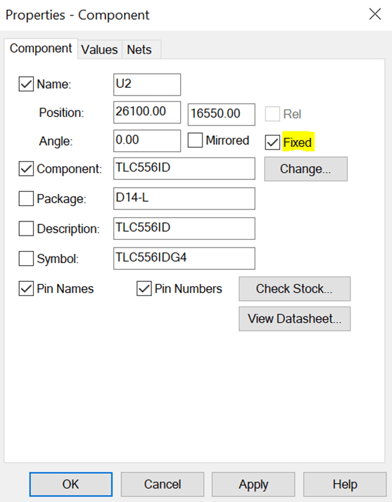
The Fix Item option is also available on the shortcut menu for a selected component.
4. Use Autoplace option
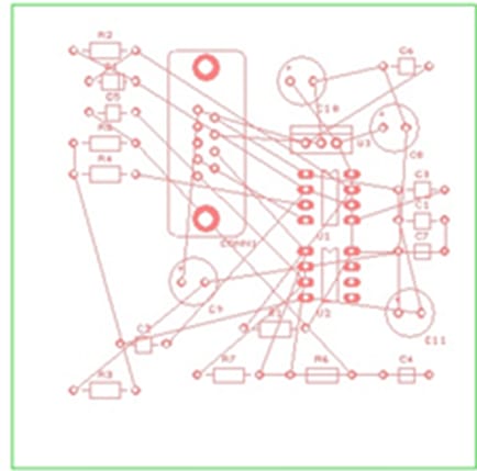
In our example we’ve placed some of the critical components and fixed them in-place. Now we will place the remaining components using the Auto place option.
From the Tools menu select Auto Place Components > then choose All Components.
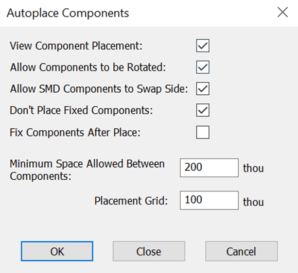
From the selection available we want to View Component Placement so check the box. Also check the Don’t Place Fixed Components box, we want the fixed components to remain in place.
Set the Minimum Space Allowed Between Components and Placement Grid values to 100 thou each. You can play about with these values if you like. Place the remaining components and use Undo if you wish to try a different placement pattern, perhaps changing the Grid to 50 thou.
Press OK to make the placement. The remaining components are placed around the fixed ones in the space available.