How can I import a board outline as a DXF?
Follow tutorial
 Dave from DesignSpark
How do you feel about this tutorial? Help us to provide better content for you.
Dave from DesignSpark
Thank you! Your feedback has been received.
Dave from DesignSpark
There was a problem submitting your feedback, please try again later.
Dave from DesignSpark
What do you think of this tutorial?
This tutorial requires:
DesignSpark PCB V11.0.0Importing your DXF board outline
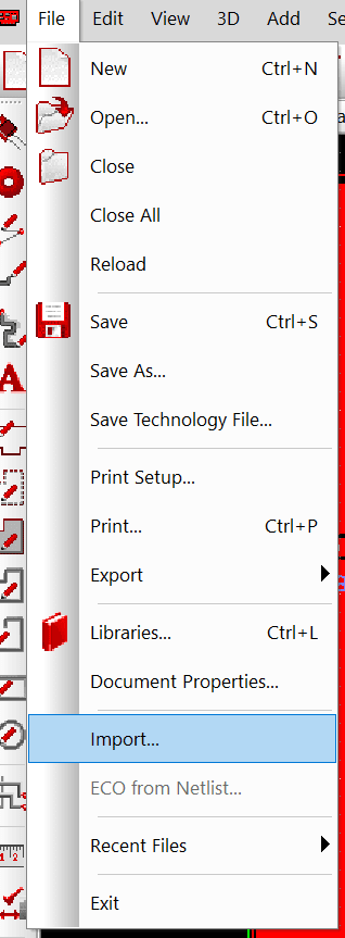
In DesignSpark PCB on your PCB layout tab, delete any PCB board outline and select File -> Import from the menu bar. Select the required DXF file.
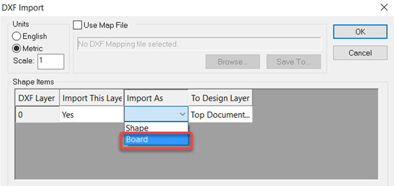
On the window that opens, select for the “Import As” options type “Board”.
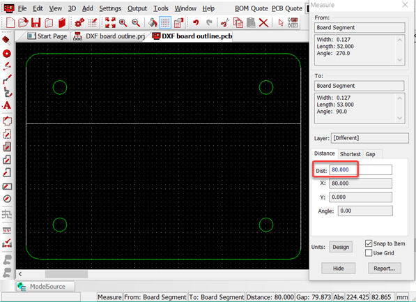
The board outline will now appear on the PCB layout, this can be selected, and positioned as required. Check a board outline dimension to ensure the process is correct, this is easily done with the measure tool.
Using DesignSpark Mechanical to create a board outline
*Please check if DesignSpark Mechanical can export the DXF format at your subscription tier
For complex board outlines it is often more convenient to design the board outline, cut outs and holes in a mechanical CAD package. DesignSpark Mechanical is ideal for this as you simply need to work in the 2D plane. Below is a simple example to illustrate the steps.
First create your board outline as required.
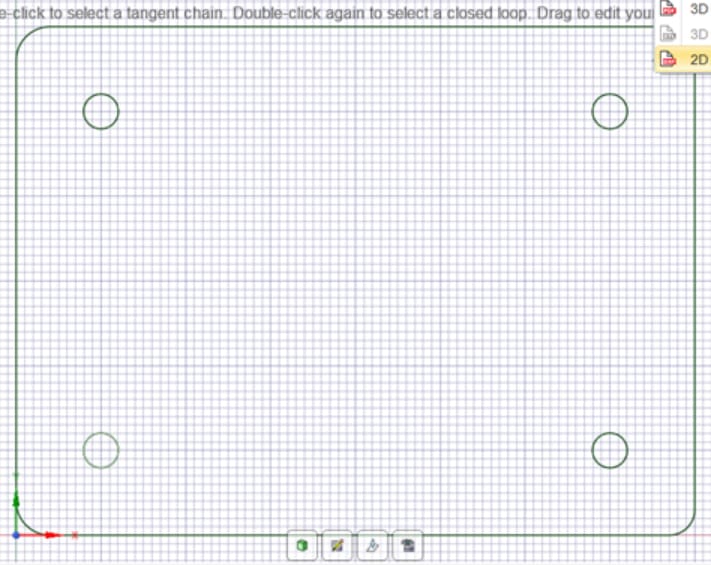
From Export Options select 2D AutoCAD (*.DXF), this will then open a File Save window with various options.
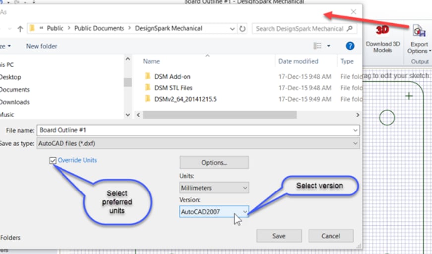
Check that the ‘units’ are as required for your DesignSpark PCB design and select the AutoCAD format version, 2007 is suitable for most purposes as a basic DXF format.
Any mechanical CAD system can be used that produces DXF files provided they conform to the DXF standard as defined by AutoCAD. Should you experience any issues try an alternative AutoCAD DXF version.