Give your Robot the Mobility Control of a real Mars Rover: Part 4
Follow article
 Dave from DesignSpark
How do you feel about this article? Help us to provide better content for you.
Dave from DesignSpark
Thank you! Your feedback has been received.
Dave from DesignSpark
There was a problem submitting your feedback, please try again later.
Dave from DesignSpark
What do you think of this article?
Mars Rover 2020
Credit: NASA/JPL
Wheeled robots take many forms: 2-, 3-, 4-, 6- or 8-wheels, with and without suspension. The type of terrain the robot will move over largely determines the choice: a nice, smooth warehouse floor or a rough, unpredictable Martian surface?
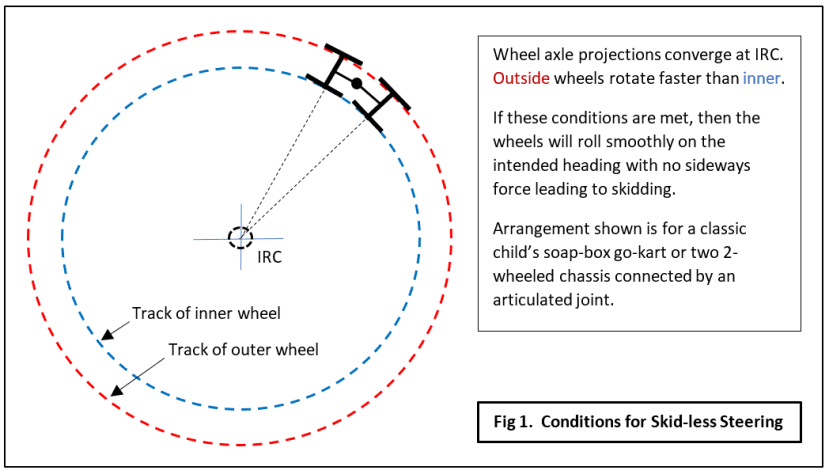
Steering methods fall into two main categories: explicit or differential. Each of these can be further divided into true or skid. The choice between true and skid steering is governed by the task to be performed by the robot. Both are suitable for any type of terrain, but if motion has to be precise and accurately measured then with the exception of 2-wheeled machines, some form of explicit steering mechanism will need to be provided. In all cases, there must be a single Instantaneous Rotation Centre (IRC) in the design. Any autonomous or semi-autonomous exploration vehicle needing accurate positioning will have to be designed this way. The IRC concept is really easy to understand and can be illustrated graphically without the need for complex mathematics. Fig.1 shows how a simple articulated four-wheel cart can be steered without any sideways skidding forces.
4-Wheel robots
In Fig.2 we have three further variations of a simple 4-wheeled mobile robot: one can be steered with precision, another is less precise but far more manoeuvrable.
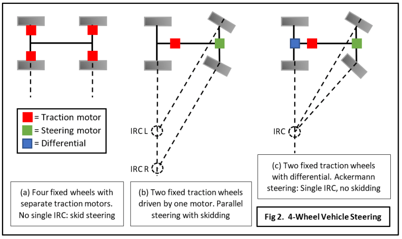
Configuration (a)
Fixed wheels with independent motors. Here we can use Differential Steering which means driving the motors on one side at a different speed from those on the inside. This meets one requirement of true steering but not the need for each front wheel to be rotating in the same direction as the turn. In other words, the wheels continue to roll straight ahead, but the speed difference is forcing them sideways. Eventually, this sideways force overcomes the friction and the vehicle skids onto its new heading. Normally used on tracked vehicles, it’s also called ‘Tank Steering’.
Features of Skid Steering
- Enables very rapid changes of direction, at the cost of extra motor power.
- With wheels on each side rotating in opposite directions, the vehicle can spin on the spot.
- All-wheel drive good for rough terrain.
- Simple design with no complex mechanical linkages.
- Renders odometry via rotation sensors very inaccurate.
- Can lead to excessive tyre wear.
Configuration (b)
Front wheels are swivelled by a steering motor and kept parallel to each other. Rear wheels are driven at the same speed with a single traction motor. This sort of ‘halfway house’ may still be quite simple and needs fewer motors, but has all the drawbacks of (a) and none of the advantages. The parallel steering wheels mean there are two IRCs, forcing one or both to skid.
Configuration (c)
Front wheels are swivelled by a steering motor, but with an Ackermann linkage arrangement ensuring wheel alignment for a single IRC. The rear wheels are again driven by a single traction motor, but via a differential unit which allows them to rotate at different speeds depending on the steering input.
Features of True Steering
- Elimination of all side-skidding forces.
- Precise and predictable turns.
- Accurate odometry.
- Mechanical complexity.
- Minimum turning circle larger than for skid steering.
- Differential action can cause total loss of drive if one driving wheel leaves the ground or loses grip.
6 to 8-Wheels
The principles described above can be applied to vehicles with 6 or 8 wheels. For skid-steering, this amounts to no more than extra motors or drive couplings. Design for true steering and things get incredibly complex if you stick to the single traction motor model: 6 or 8 wheeled vehicles will normally require the front 4 or 6 wheels respectively to steer, and multiple differentials in the drivetrain complicate matters further. Military trucks are usually built this way because mechanical repairs and ‘bodges’ are easier for non-technical personnel in the field than electronic/electrical systems. In wartime, these vehicles are expendable and very long-term reliability is not required. Planetary exploration rovers must be simpler mechanically (less weight) and much more reliable (no repairs possible).
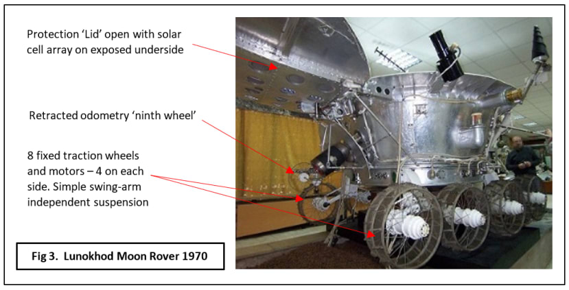
Rover designers are faced with weight limitations for two reasons: every extra gram increases the launch fuel costs, and too much ground pressure could see wheels sinking into a soft, dusty lunar or Martian surface. Lightweight and less robust structures can reduce the first problem, while multiple wheels or even caterpillar tracks can help with the second. Tracks are generally ruled out because precise navigation is needed and high-speed manoeuvrability is not. Having said that, the very first off-planet rover, Lunokhod 1 which landed on the Moon in November 1970, did feature 8-wheels and skid-steering (Fig.3). And yes, it does look like it was made out of a galvanised tin bath. Nevertheless, it worked and travelled for over 6 miles. Lunokhod 2 managed over 26 miles in just four months.
Lunokhod and the Mars Rovers
The Lunokhod rovers had 8 fixed wheels, each driven by its own electric motor. The motors on each side all ran at the same speed; skid-steering being achieved by varying the speed between the two sides. Odometry was obtained from a ninth non-driven castor wheel trailing along behind. This arrangement proved less than satisfactory and was later shown to have underestimated the distance travelled by some margin.
There were no more rovers until 1997 when the NASA Pathfinder mission put the 6-wheeled Sojourner on Mars. Sojourner was toy-sized, only 65cm long by 48cm wide, a technology demonstrator for the new generation of planetary landers that could move around and explore. After that came the larger Spirit and Opportunity in 2004 followed by the even larger nuclear-powered Curiosity in 2012 (Fig.4). Curiosity’s successor is due to touch down in 2020. All these rovers share the same 6-wheeled mobility system based on a ‘Rocker-Bogie’ suspension.
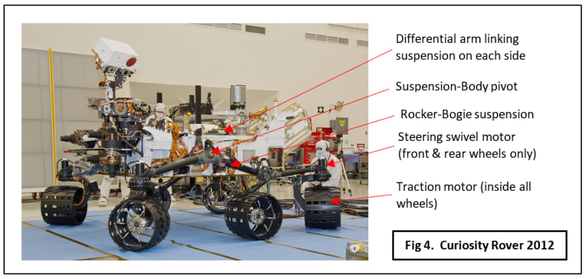
Notice that the four ‘corner’ wheels are used for steering. In this pre-launch picture, Curiosity is set with its wheels positioned for a turn on the spot. A limitation of this rover’s mobility system is that the motor controller can’t drive the traction motors at the same time as the steering. Having to stop every time a course adjustment has to be made makes for slow progress, and at the time of writing Curiosity has clocked up just over 12 miles since it landed six years ago. Compare that with the second Lunokhod’s progress…. Of course, their mission objectives were somewhat different: science took a back seat in the Cold War of the 1970’s. Setting records or ‘being first’ was all that mattered. The Soviet Union lost the race to put a man on the moon, but it could have the most travelled robot lunar rover! Curiosity (originally called the Mars Science Laboratory) needed to move with precision as scientific data gathering was the top priority.
Also in this 6-wheel section, we have the European ExoMars 2020 rover. Take a look at its picture heading up Part 2 of this series. The wheel arrangement seems broadly similar to that of the NASA rovers but there are big differences. For a start, there is no rocker-bogie suspension, just three 2-wheel bogies each pivoted in the centre. The front four wheels are attached to bogies on each side; the rear wheel bogie is pivoted on the back of the rover so it swings at right angles to the others. As with the other Mars rovers, there are traction motors on all six wheels. Unlike the others, all wheels can be steered allowing ‘crab’ movements, and the suspension ‘legs’ independently swung back and forth providing a ‘walking’ gait. The rover will also be able to drive all traction and steering motors at the same time. This paper contains a lot more detail on the mobility systems for the ExoMars rover, now due to land on Mars in 2020.
Fun on Two Wheels
I’ll skip 3-wheelers as they’re not suitable for rough terrain – only smooth warehouse floors. The same can be said of a 2-wheeled buggy type robot featuring one or two castor wheels to keep it upright (See Part 2). Most educational, hobby and research robots use this configuration because it’s so easy to work with. Despite being based on differential steering it has a single IRC and merely by adjusting the relative speeds and rotational direction of its two wheels, motion can be varied from a straight line to spinning on the spot. No good on Mars, but great for learning and research.
Suspension
Most small commercially available mobile robots do not feature any kind of suspension. That’s OK for smooth floors, but what about ‘off-road’? Cars usually have a short-travel (up and down movement) spring and damper on each wheel with a ‘stiff’ setting for sports cars allowing fast cornering and ‘soft’ for road cars providing better ride comfort. Off-road vehicles have long-travel suspension, a greater ride height to cope with rough terrain and all-wheel drive. A planetary rover needs these off-road features too. The Lunokhod rover’s short-travel independent suspension is more like that of a road car because it was designed for real-time remote control allowing obstacles to be avoided, not clambered over. As I suggested earlier, it was built for speed on a soft, dusty surface.
The Mars rovers were built to move over a hard, rock-strewn terrain and if necessary climb over obstacles, not go around them (Fig.5). The main reason for this is that these rovers have got mission objectives to reach pre-determined points away from the landing site, and having to navigate around every small rock on the way may mean these tasks are never accomplished. A suspension system had to be designed which would keep all six wheels firmly in contact with the terrain under all conditions.
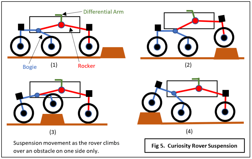
Rocker-Bogie suspension allows Curiosity to get over obstacles taller than the wheel diameter, there are no springs and the assembly on each side is suspended from the body at just one pivot point. Each side is not completely independent of the other, however: across the top of the body is a centre-pivoted horizontal beam linking the two Differential arms. This prevents the body randomly swinging on the two side pivots and also transfers the motion of the Rocker arm from one side to the other. When one front wheel climbs over a rock, the Differential arm moves back, rotating the beam which in turn forces the Rocker on the other side down, partially levelling the body and increasing the ground pressure of its front wheel. An interesting point about the design is that greater traction would have been achieved by running Bogie-first. I’m not sure whether this was discovered by accident or design, but the Rocker-first configuration is quite deliberate. If Curiosity gets stuck on a loose surface, it should be able to reverse out of trouble thanks to the greater traction available going backwards. This paper describes the mobility system for the basically similar MERs, Spirit and Opportunity.
Build Your Own Rover
Real robots are becoming incredibly complex machines, mechanically and electronically, requiring evermore sophisticated programming (coding) to make them carry out useful tasks. Most commercial ‘hobby’ mobile robots tend to be of the 2-wheel buggy with castor, or 4-wheel with no explicit steering format. None that I know of feature any kind of suspension system. The buggy type is easy to make from scratch and is great for developing control software and trying out sensor, navigation and communication systems. If you fancy a ‘proper’ Mars rover, a miniature Curiosity, NASA/JPL have come up with a complete open-source design package requiring about £2000 worth of components. Expensive for an individual, but ideal for college or university STEM teaching.
Finally
Planetary explorer rovers are designed to be robust and reliable because by definition they work in an undocumented, hostile environment with no possibility of maintenance. The MER rover Opportunity which landed in 2004, was still operating and gathering useful data until June this year, 2018. It went into hibernation mode from which it will hopefully emerge, when a global sandstorm engulfed the planet (a not uncommon occurrence), cutting off the sunlight from its solar panels. In that time, it became the furthest-travelled rover, covering over 28 miles and beating Lunokhod’s record. Curiosity, meanwhile, being ‘nuclear-powered’, carries on regardless. Here’s hoping ‘Oppy’ wakes up soon.
If you're stuck for something to do, follow my posts on Twitter. I link to interesting articles on new electronics and related technologies, retweeting posts I spot about robots, space exploration and other issues.