Getting started with Maxim EE-Sim® OASIS Part 1: Introduction & Simulation
Follow article
 Dave from DesignSpark
How do you feel about this article? Help us to provide better content for you.
Dave from DesignSpark
Thank you! Your feedback has been received.
Dave from DesignSpark
There was a problem submitting your feedback, please try again later.
Dave from DesignSpark
What do you think of this article?

Evaluating Maxim’s EE-Sim OASIS switchmode power supply simulator tool, and using it to design a SMPS for a Raspberry Pi.
What is EE-Sim OASIS?
Maxim EE-Sim OASIS is an offline SPICE-like circuit simulation tool, provided free-of-charge for simulation of switchmode power supply (SMPS) circuits that utilise Maxim switching controllers. The OASIS tool is provided as part of the EE-Sim toolkit, and goes hand-in-hand with the online “DC-DC Converter Tool” which allows for parametric design of SMPS circuits.
EE-Sim OASIS has an edge over more common SPICE simulation tools, such as LTspice, due to the SIMPLIS engine that runs the simulation. SIMPLIS was designed from the outset to be used to simulate switching power supplies using a technique called Piecewise Linear Modelling – where the circuit is treated as a linear circuit at every sample point, whereas SPICE is a more generic simulation engine suited for doing analogue circuit simulation. This difference means that the SIMPLIS engine is far quicker at generating load-step analysis results, and is capable of doing AC loop analysis with far less effort to set up the simulation when compared to traditional SPICE tools.
In particular, EE-Sim OASIS is easy to use due to the vast library of tested, ready to go examples that are included for buck, boost, buck-boost and isolated converter topologies, all utilising Maxim switching controllers.

Introduction to EE-Sim OASIS

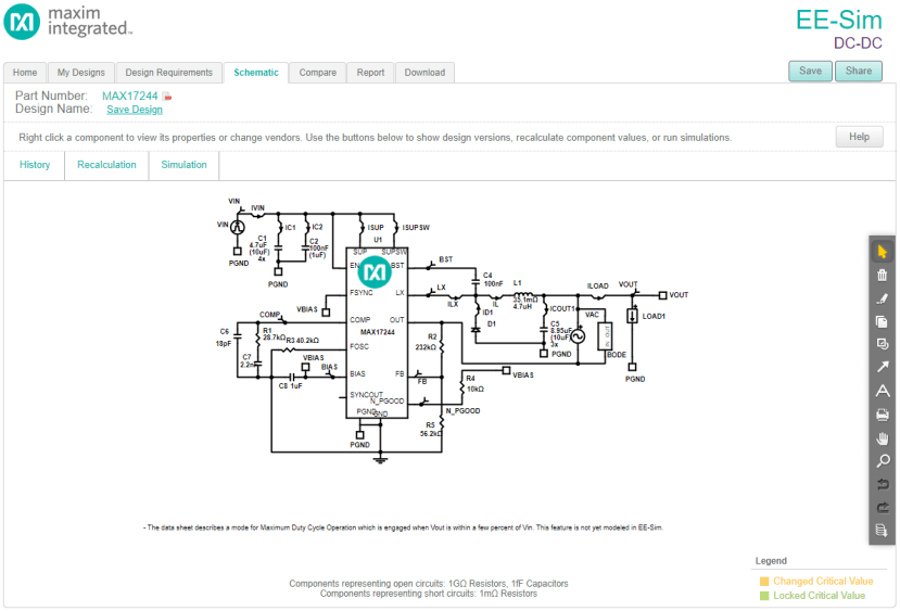
If we open one of the reference designs provided, in particular the “MAX17244 Load Step Transient” this opens a schematic view, with notes helpfully included. This interface will look familiar to anyone who has used simulation tools previously. A wide variety of additional components are also included within the package, so that full circuits can be built up and simulated.
Maxim included detailed notes within the schematic, explaining various parts of this, such as what the “BODE” and “VAC1” components do, and how to change various settings for the simulation.
As we have opened this example, we can run the default simulation setup to see what simulation outputs are given. This opens another small window which shows the SIMPLIS simulation status, and then waveforms open alongside the schematic.

To do a load step transient simulation with 18 probes took only 10 seconds, which in a conventional SPICE tool would take a lot more time and effort to set up and run.
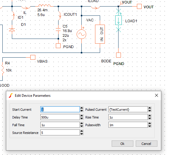
Here we are reconfiguring the load current device in preparation for setting up a multi-step simulation. This is easily done with EE-Sim OASIS and allows for testing of various situations. A parameter called “TestCurrent” has been created that is connected to the “Pulsed Current” device parameter. This particular multi-step simulation will allow us to discover how the switching controller will behave in an overcurrent situation.
Once created, we go into the “Simulator” menu, then “Setup Multi-Step” option, which opens a window where the parameter name and values can be entered.
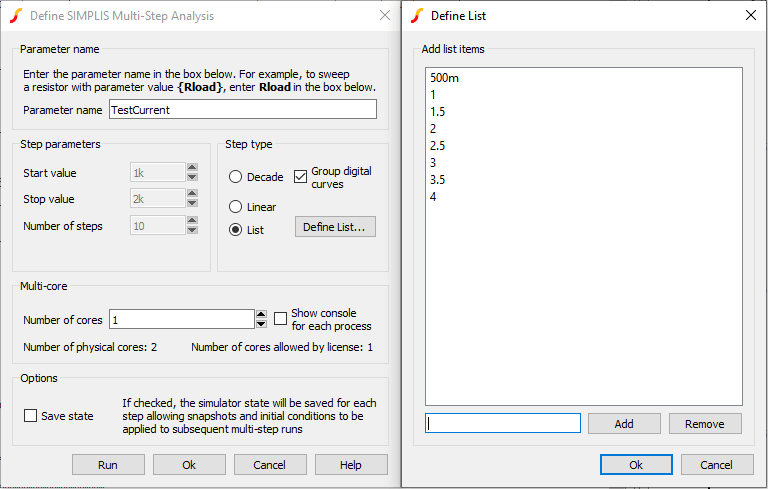
Once you have entered the desired test values, click the “Run” button and the multi-step analysis will begin. To complete 8 different current simulations took under two minutes to complete, enabling quick improvement cycles.
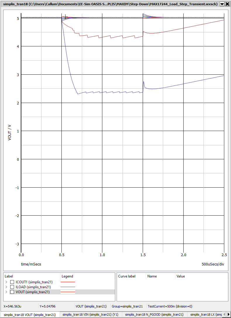
The waveform output is then shown once the simulation has completed, where annotations and cursors can be added to any waveform. The waveforms can also be stacked in various combinations, making it easy to determine the operation of a design.
Designing a SMPS
Alongside the many provided reference designs is the ability to use the online “DC-DC Converter Tool” provided by Maxim, which creates designs to a set of parameters you provide, which can then be opened within EE-Sim OASIS for further analysis and adjustment.
To begin, we decided upon designing, simulating and constructing a switching power supply capable of taking 9-30VDC input range with a nominal voltage of 12V, and producing 5.1V at 2.5A, suitable for powering a Raspberry Pi. This would enable powering of a Raspberry Pi from a car with a 12V outlet, or larger vehicles that often have 24V sockets, or even an industrial setting as controls are commonly run at 24V. The output voltage of 5.1V was picked as this allows some headroom for cable voltage losses, and the standard USB voltage is 5V +/- 5%, meaning the permitted voltage range is 4.75V to 5.25V.
Initial Design
We started the design work in Maxim’s online utility, which greatly simplifies the design process.
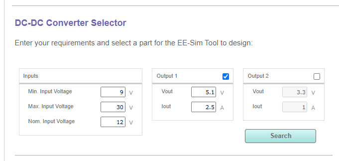
Once the appropriate design inputs have been entered, a more detailed window appears that has more options, including the type of switching controller, and other selectable features that the controller has. A list of controllers that match the entered design parameters is visible below.
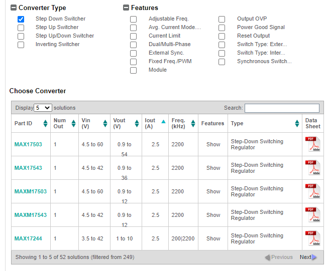
One downside to this is that the IC footprints are not listed, which although can be found in the datasheets linked on the far right, means you have to click into each datasheet individually. Based upon these results and with information from the datasheet, we settled upon the MAX17244 – this meets our design requirements and comes in a package that facilitates PCB assembly with relative ease.
Once selected, the tool then produces a schematic with appropriate component values filled in, ready to run simulations.
From here, we can download the schematic, pre-configured for various different simulation types. Another advantage to being able to download the schematic and open it in EE-Sim OASIS, is that other components can be added to the design, and we can also add additional probes if we need to simulate operation of other parts of the circuit.
Testing & Tweaking the Design
We can see below the generated schematic, and output waveforms that have been simulated in EE-Sim OASIS. Note there is a slight over & undershoot on the output supply when stepping the current from 1.25A to 2.5A. The flexibility of OASIS means that we can adjust component values, and add & remove components to see if we can reduce this over/undershoot.

We can also go back to the online tool, and change the output requirements. To get tighter regulation of the output, the “Output Voltage Load Step Over/Undershoot” percentage was changed to 2%, and the “Output Voltage Ripple” was left set at the default 2%. The load step start current, and step current were changed to 0.5A, and 1.7A respectively; this is in line with the figures that the Raspberry Pi Foundation provide for the current consumption of the Raspberry Pi 3B+. This produced a much better looking output, with a greatly reduced over/undershoot.

EE-Sim OASIS also allows for quick AC simulation of the power supply design, and produces a Bode plot which can be interpreted to understand the stability of the power supply. Based upon the produced plot, we can see that the power supply should be stable once constructed.

Conclusion
In part 2 of this series, we will look at performing schematic capture for the SMPS, and designing a PCB suitable for connecting to a Raspberry Pi, then in part 3, we will look at PSU assembly and testing.